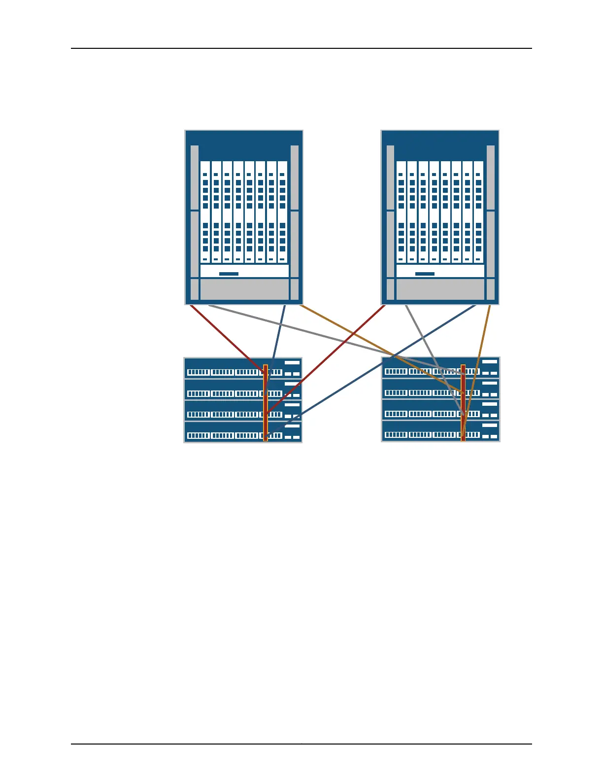
Figure 84: QFX3008-I Interconnect Device Control Plane Connections
VC0
VC1
c0
ge-3/0/39
ge-1/0/39
ge-2/0/39
ge-3/0/39
ge-0/0/39
IC0
IC1
ge-2/0/39
ge-0/0/39
ge-1/0/39
CB0
CB1
CB0
CB1
g041123
Port 0 Port 1
Port 0
Port 1
Port 0 Port 1
Port 0
Port 1
Specific ports have been reserved on the Virtual Chassis to connect to the Interconnect
devices, QFX3500 Node devices, and QFX3100 Director devices in your QFabric system.
Such design simplifies installation and facilitates timely deployment of a QFabric system.
It also enables the use of a standard Virtual Chassis configuration (see Example:
Configuring the Virtual Chassis for the QFabric Switch Control Plane).
Before you begin to connect a QFX3008-I Interconnect Device to the control plane
network:
•
Install your QFabric system hardware. For more information, see “Installing and
Connecting a QFX3100 Director Device” on page 213, “Installing and Connecting a
QFX3008-IInterconnect Device”on page223, and “Installing and Connecting a QFX3500
Device” on page 259.
•
Install your Virtual Chassis hardware. For more information, see Installing and
Connecting an EX4200 Switch.
•
Create two Virtual Chassis of four EX4200 switches each. For more information, see
Configuring an EX4200 or EX4500 Virtual Chassis (CLI Procedure).
279Copyright © 2012, Juniper Networks, Inc.
Chapter 22: Cabling the QFabric Switch