Table 82 on page 401 describes the QSFP+ uplink port LEDs.
Table 82: Uplink Port LEDs on QSFP+ Uplink Ports on a QFX3500 Device
DescriptionStateColorLED
No link is established, there is a fault, or the link is down.
NOTE: The LED remains unlit only if all four of the 10-Gigabit Ethernet
SFP+ breakout links are down.
OffUnlitLink/Activity
A link is established, but there is no link activity.
NOTE: The LED is lit green when at least one of the four 10-Gigabit Ethernet
SFP+ breakout links is established.
On steadilyGreen
A link is established, and there is link activity.
NOTE: The LED is lit green when at least one of the four 10-Gigabit Ethernet
SFP+ breakout links is established.
Blinking
No transceiver is installed in the port, or the transceiver is not supported.OffUnlitStatus
A transceiver is installed in the port.On steadilyGreen
Related
Documentation
Rear Panel of a QFX3500 Device on page 66•
• Installing a Transceiver in a QFX Series Device on page 374
• Connecting a Fiber-Optic Cable to a QFX Series Device on page 377
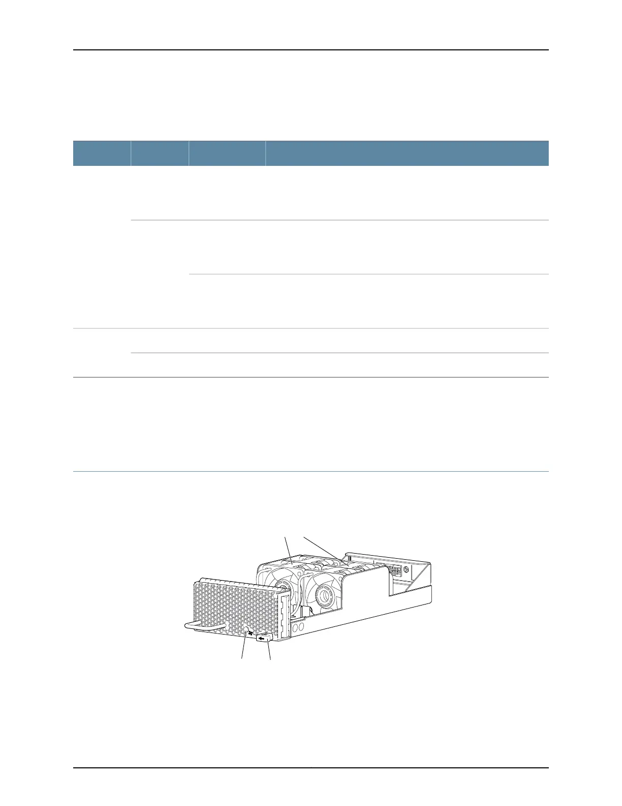
Fan Tray LED on a QFX3500 Device
Figure 141 on page 401 shows the location of the LED on the fan tray.
Figure 141: Fan Tray LED in a QFX3500 Device
g050011
Fan modules
EjectorLED
Table 83 on page 402 describes the function of the fan tray LED.
401Copyright © 2012, Juniper Networks, Inc.
Chapter 32: Viewing QFX3500 System Information