CHAPTER 31
Viewing QFX3008-I System Information
•
Chassis Status LEDs on a QFX3008-I Interconnect Device on page 387
•
Control Board LEDs on a QFX3008-I Interconnect Device on page 389
•
16-Port QSFP+ Front Card LEDs on a QFX3008-I Interconnect Device on page 391
•
Rear Card LEDs on a QFX3008-I Interconnect Device on page 393
•
AC Power Supply LEDs on a QFX3008-I Interconnect Device on page 394
•
Wiring Tray LEDs on a QFX3008-I Interconnect Device on page 395
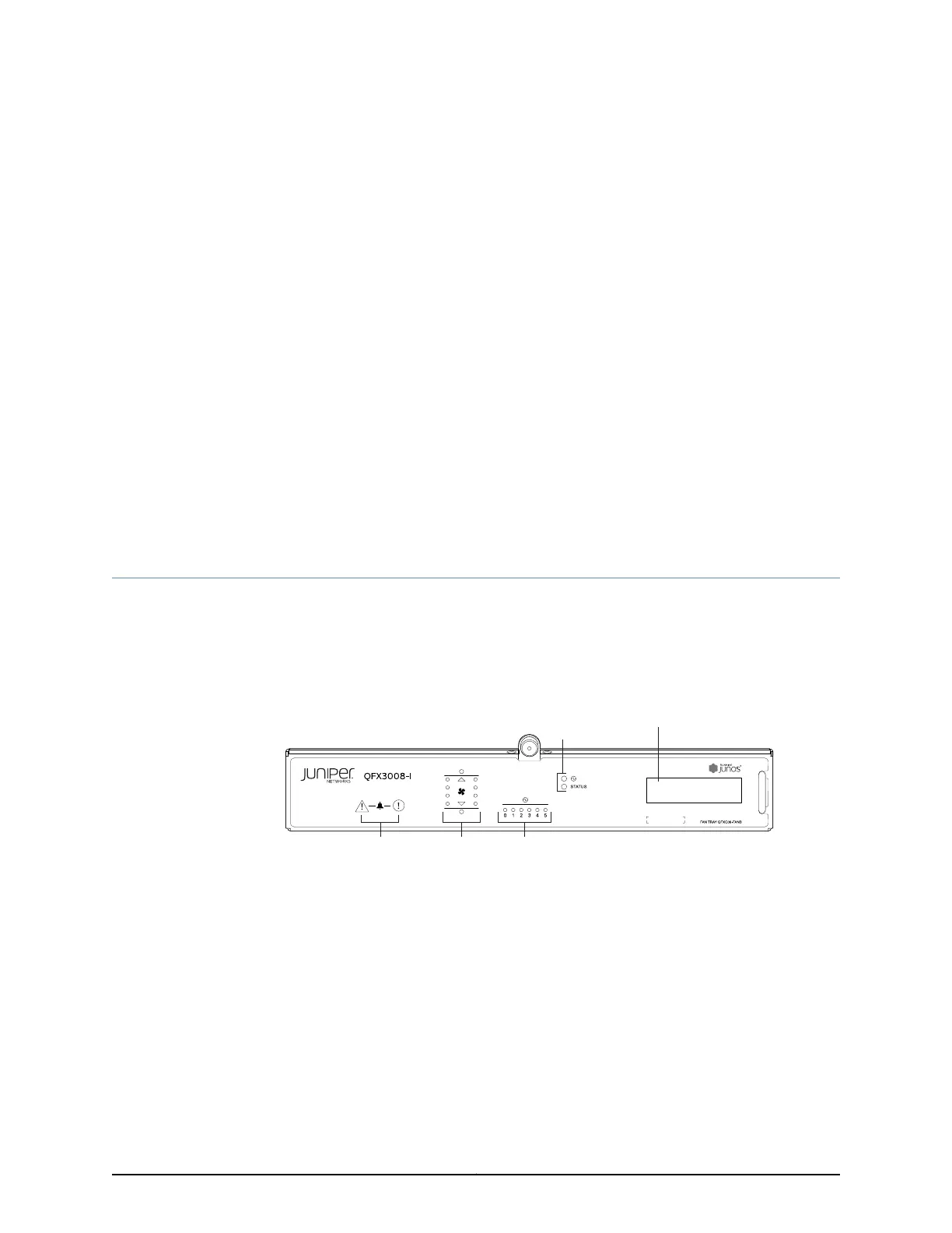
Chassis Status LEDs on a QFX3008-I Interconnect Device
The front panel of the chassis of a QFX3008-I Interconnect device has four sets of
informational LEDs to the left of the LCD panel.
See Figure 130 on page 387.
Figure 130: Chassis Status LEDs
g050105
Power supply
LEDs
System
LEDs
Fan
LEDs
Alarm
LEDs
LCD panel
Table 71 on page 388 describes the chassis status LEDs in a QFX3008-I Interconnect
device, their colors and states, and the status they indicate.
387Copyright © 2012, Juniper Networks, Inc.