BeneVision N22/N19 Patient Monitor Operator’s Manual 19 - 5
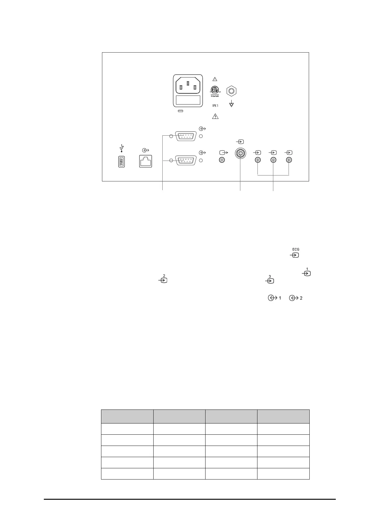
The following figure shows the rear housing connectors of the Vigilance II monitor.
To connect the Vigilance II monitor, follow this procedure:
1. Connect the end of the CCO/SvO
2
cable marked CN1 to the CCO/SvO
2
module.
2. Insert the ECG signal end of the CCO/SvO
2
cable into the ECG signal input port marked on the rear
housing of the Vigilance II monitor.
3. Insert the MAP signal end of the CCO/SvO
2
cable into the analog signal input port 1 marked , the CVP
signal end into port 2 marked , and SpO
2
signal end into port 3 marked respectively on the rear
housing of the Vigilance II monitor.
4. Insert UART end of the CCO/SvO
2
cable into either of the serial ports (marked or ) on the rear
housing of the Vigilance II monitor.
5. Enter the
Serial Port Setup menu of the Vigilance II monitor, and make the following settings:
◆ Device: IFMout
◆ Baud Rate: 19200
◆ Parity
: None
◆ Stop Bits: 1
◆ Data Bits: 8
◆ Flow Control: 2 seconds
6. Enter the Analog Input Setup menu of the Vigilance II monitor, and set port 1, port 2 and port 3 as follows:
(1) Serial ports (2) ECG signal input port (3) Analog signal input ports
Setting Port 1 Port 2 Port 3
Parameter MAP CVP SaO
2
Voltage Range 0-5 v 0-5 v 0-10 v
Full Scale Range 500 mmHg (66.7 kPa) 100 mmHg (13.3 kPa) 100%
Simulated High Value 500 mmHg (66.7 kPa) 100 mmHg (13.3 kPa) 100%
Simulated Low Value 0 mmHg (0.0 kPa) 0 mmHg (0.0 kPa) 0%
100-240V-
50/60Hz,1.0A
T1AL 250V
12
3
ECG
1
2
(1) (2) (3)