Menu Tables
462
FQ2-S/CH User’s Manual
I/O setting
I/O setting
Output
OUT0 Polarity You can change the polarity of the output
signals that are assigned to OUT0 to
OUT2 (regardless of what signal is
assigned to the output).
When FQ-SDU is connected, OUT0 to 2
will not appear.
Positive (Default)
Negative
System ---*
1
OUT1 Polarity Positive (Default)
Negative
System
OUT2 Polarity Positive (Default)
Negative
System
BUSY LED You can change the BUSY indicator to a
RUN indicator.
BUSY (Default)
RUN
System
---*
1
Output control You can select the data output method.
(Only when the FQ-SDU1 is con-
nected.)
None (Default)
Handshaking
Sync. Output
System ---*
1
Output period Sets the period for outputting measure-
ment results. (Only when the FQ-SDU1
is connected.)
2.0 to 5,000.0 ms
10.0 ms (Default) System
---*
1
GATE ON delay
Sets the time from when the result is out-
put to the parallel interface until the
GATE signal turns ON.
(Only when the FQ-SDU1 is con-
nected.)
1.0 to 1,000.0 ms
1.0 ms (Default)
System ---*
1
Output time
Sets the time to turn ON the GATE sig-
nal.
(Only when the FQ-SDU1 is con-
nected.)
1.0 to 1,000.0 ms
5.0 ms (Default)
System ---*
1
Timeout
Sets the timeout time for output control.
(Only when the FQ-SDU1 is con-
nected.)
0.5 to 120.0 s
10.0 s (Default) System ---*
1
Number of delay
Set the number of times to ignore the
TRIG signal turning ON between when
the TRIG signal turns ON and the mea-
surement results are output.
(Only when the FQ-SDU1 is con-
nected.)
1 (Default) to 15 System ---*
1
ACK signal ON
period
Sets the output time of the normal execu-
tion completion signal for parallel com-
mands.
(Only when the FQ-SDU is connected.)
1.0 to 1,000.0 ms
5.0 ms (Default) System ---*
1
Output polarity
Sets the ON/OFF polarity for all of the
output signals
(Only when the FQ-SDU is connected.)
Positive (Default)
Negative System ---*
1
Input
Input mode Specifies whether to use functions other
than scene switching for external parallel
commands.
Standard mode (Default)
Expanded mode
System ---*
1
Output data setting
Noprotocol data output
Output data set --- Data 0 to data 31 Scene
---*
1
[MENU]
Data settings
Sets data to output to selected data num-
ber.
Text strings for the filter items, position
compensation items, inspection items
and expression that are set
Scene
Multi-data
setting Scene
Rename Changes the name of the selected data
number.
The name can be changed to a name
with up to 15 alphanumeric characters.
Scene
Copy Copies the contents registered in the
selected data number to another data
number.
Scene
Delete
Clears the content of the selected data
number.
Scene
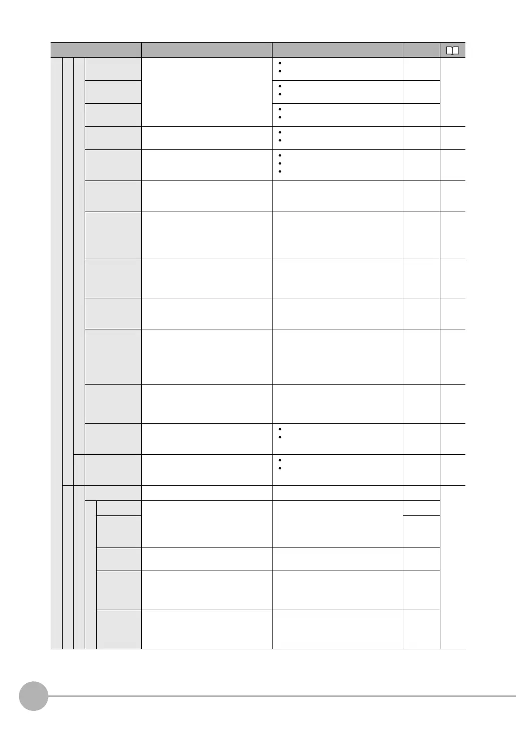
Menu command Description Setting range Data

 Loading...


