Menu Tables
470
FQ2-S/CH User’s Manual
Sensor settings
Data output
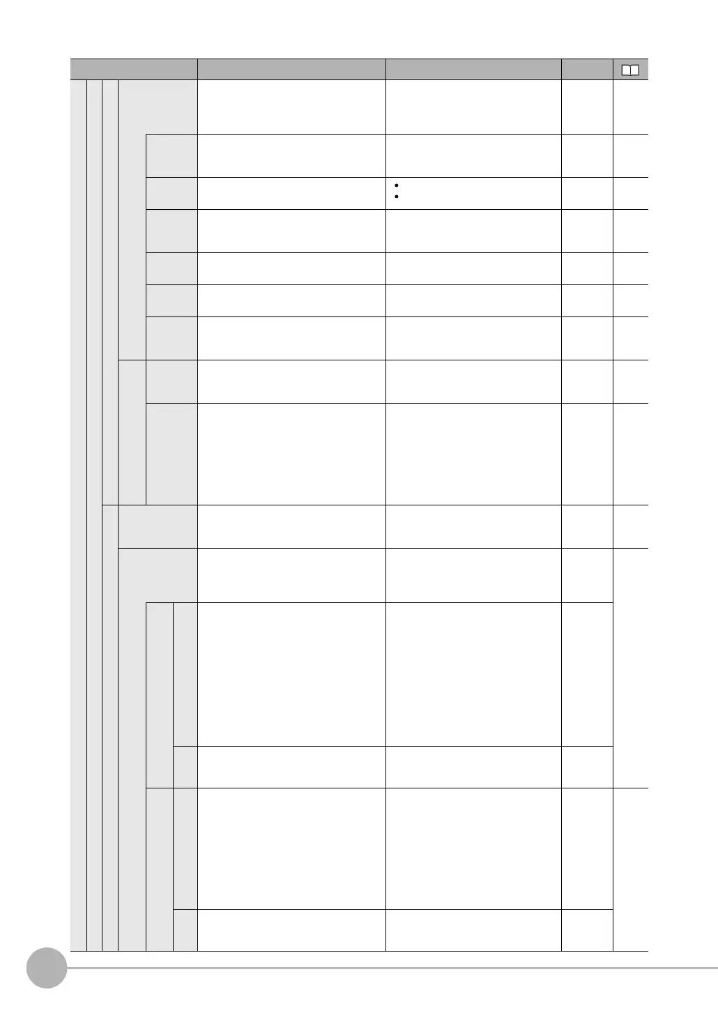
No-protocol data
When the com-
munications type
is RS-232C no-
protocol
Baud rate
Set the baud rate to use for RS-232C
communications.
2400, 4800, 9600, 19200,
38400, 57600, or 115200
(Default: 38400)
System ---*
1
Data
length
Sets the data length. 7bit
8bit (Default: 8bit)
System ---*
1
Parity Sets the parity.
None
Odd
Even (Default: None)
System ---*
1
Stop bit Sets the number of stop bits. 1bit
2bit (Default: 1bit)
System ---*
1
Flow con-
trol
Sets the controls for the flow of communi-
cations with the software.
None
Xon/Xoff (Default: None)
System ---*
1
Delimiter
Set the delimiter to add to the end of com-
mands and responses.
CR
LF
CR+LF (Default:CR)
System ---*
1
When the communications type
is RS-232C no-protocol
Interval
timeout
(text)
Timeout [s] Set the time in seconds to
generate a timeout error.
1 to 120 s, 0: Not monitored.
(Default: 0 s) System ---*
1
Interval
time-
out(after
Xoff
reception)
Timeout [s] Set the time in seconds to
generate a timeout error.
1 to 120 s, 0: Not monitored.
(Default: 0 s) System ---*
1
Link data output
Communication
type
Sets the communications type to use for
EtherNet/IP outputs.
Invalid (Default)
PLC link (SYSMAC)
PLC link (MELSEC)
System ---*
1
Area set-
tings(Only when
communications
type is PLC Link)
---*
1
Command
Area type
Sets the area to write command data to
the Sensor.
Control inputs, command codes, and com-
mand parameters are written to this area.
PLC Link (SYSMAC CS/CJ/CP/One)
CIO Area (CIO) (Default)
Work Area (WR)
Holding Bit Area (HR)
Auxiliary Bit Area (AR)
DM Area (DM)
EM Area (EM0 to EMC)
PLC Link (MELSEC QnU/Q/QnAS)
Data Register (Default)
File Register
Link Register
System
Address
Set the first address of the command area.
0 to 99,999 (Default: 0) System
Response
Area type
Sets the area to write execution results
from the Sensor.
Control outputs, command codes,
response codes, and response data
PLC Link (SYSMAC CS/CJ/CP/One)
CIO Area (CIO) (Default), Work Area
(WR), Holding Bit Area (HR), Auxil-
iary Bit Area (AR), DM Area (DM),
EM Area (EM0 to EMC)
PLC Link (MELSEC QnU/Q/QnAS)
Data Register (Default)
File Register
Link Register
System
---*
1
Address
Set the first address of the response area. 0 to 99999 (Default: 100)
System
Menu command Description Setting range Data

 Loading...

