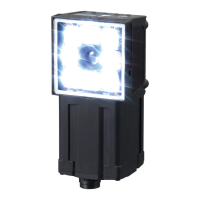
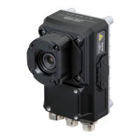
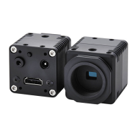
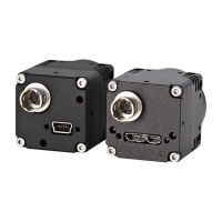
Specifications and Dimensions
FQ2-S/CH User’s Manual
551
Appendices
9
I/O specifi-
cations
Input signals 7 signals
• Single measurement input (TRIG)
• Control command input (IN0 to IN5)
Output signals 3 signals
• Control output (BUSY)
• Overall judgement output (OR)
• Error output (ERROR)
Note: The assignments of the three output signals (OUT0 to OUT2) can also be changed
to the following.
・READY
・RUN
・STG (Strobe trigger)
・OR (Item0 judgment) to OR31 (Item31 judgment)
・Exp.0 judgment to Exp.31 judgment
Ethernet specifi-
cations
100Base-TX/10Base-T
Communica-
tions
Ethernet TCP no-protocol,
Ethernet UDP no-protocol,
Ethernet FINS/TCP no-protocol,
EtherNet/IP,
PLC Link, or
PROFINET
I/O expansion Possible by connecting FQ-SDU1 Sensor Data Unit.
11 inputs and 32 outputs
RS-232C Possible by connecting FQ-SDU2 Sensor Data Unit..
Input specifica-
tions
Refer to Table 2.
Output specifi-
cations
Connection
method
Special connector cables
Power supply and I/O: 1 cable
(FQ-WD)
Touch Finder and computer: 1
cable (FQ-WN)
Special connector cables
Power supply I/O and Sensor Data Unit
.s: 1 cable (FQ-WD and
FQ-WU)
Touch Finder and computer: 1 cable (FQ-WN)
Indications BUSY indicator (BUSY, green), Judgement result indicator (OR, orange), error indicator (ERROR, red),
Ethernet communications indicator (ETN, orange)
Note: The assignment of the BUSY indicator can be changed to a RUN indicator (display color: green).
Ratings Power supply
voltage
21.6 to 26.4 VDC (including ripple)
Insulation resis-
tance
Between all lead wires and case: 0.5 MΩ (at 250 V)
Current con-
sumption
2.4 A max. 0.3 A max.
Item Inspection and ID models
Model NPN FQ2-S40 FQ2-
S40-M
FQ2-
S40-08
FQ2-
S40-08M
FQ2-S40-13 FQ2-S40-
13M
PNP FQ2-S45 FQ2-
S45-M
FQ2-
S4508
FQ2-
S45-08M
FQ2-S45-13 FQ2-S45-
13M

 Loading...

