RL78/F13, F14 CHAPTER 17 LIN/UART MODULE (RLIN3)
R01UH0368EJ0210 Rev.2.10 1172
Dec 10, 2015
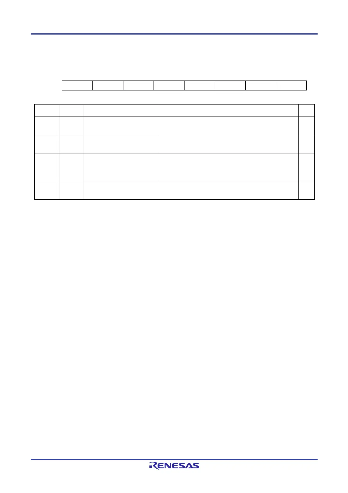
(8) UART Standby Control Register (LUSCn)
Address: F06C5H
7 6 5 4 3 2 1 0
— — — — — URDCC USEC UWC
Value after reset:
0 0 0 0 0 0 0 0
Bit Symbol Bit Name Function R/W
0 UWC UART Standby Wake-up Control 0: Disables start of reception from STOP mode.
1: Enables start of reception from STOP mode.
R/W
1 USEC UART Standby Error Control 0: Enables error detection interrupt generation.
1: Disables error detection interrupt generation.
R/W
2 URDCC UART Standby Received data
Comparison Control
0: Disables comparison of the received data and the LIDBn
register value in SNOOZE mode.
1: Enables comparison of the received data and the LIDBn
register value in SNOOZE mode.
R/W
7 to 3 — Reserved These bits are always read as 0. The write value should always
be 0.
R/W
Set the LUSCn register when the OMM0 bit in the LMSTn register is 0 (LIN reset mode).
UWC bit (UART standby wake-up control bit)
The UWC bit enables or disables transition to SNOOZE mode upon detection of the falling edge on the reception pin in
STOP mode.
With 0 set, detection of the falling edge on the reception pin in STOP mode does not cause a transition to SNOOZE mode
thus not initiating reception.
With 1 set, detection of the falling edge on the reception pin in STOP mode causes a transition to SNOOZE mode thus
initiating reception.
USEC bit (UART standby error control bit)
The USEC bit enables or disables interrupt generation upon detection of an error or change in status in SNOOZE mode.
With 0 set, if an error (framing error or parity error) or change in status (detection of the expansion bit) is detected in SNOOZE
mode, the corresponding flag is set to 1 thus generating the error detection interrupt.
With 1 set, if an error (framing error or parity error) or change in status (detection of the expansion bit) is detected in SNOOZE
mode, the corresponding flag is not set to 1 thus generating no error detection interrupt and the module makes a transition
to STOP mode.
Do not set this bit to 1 (error detection interrupt generation is disabled) when the UWC bit is 0 (start of reception from STOP
mode is disabled).
This bit is enabled when the UWC bit is set to 1 (start of reception from STOP mode is enabled).
URDCC bit (UART standby received data comparison control bit)
The URDCC bit enables or disables comparison of the data received in SNOOZE mode and the LIDBn register value.
With 0 set, the data received in SNOOZE mode is not compared with the LIDBn register value and the appropriate interrupt
is generated.
With 1 set, the data received in SNOOZE mode is compared with the LIDBn register value, and if they agree, the successful
reception interrupt is generated. If they do not agree, an interrupt is not generated but the module makes a transition to
STOP mode.
Do not set this bit to 1 (comparison of the received data and the LIDBn register value in SNOOZE mode is enabled) when
the UWC bit is 0 (start of reception from STOP mode is disabled).
When this bit should be set to 1 (comparison of the received data and the LIDBn register value in SNOOZE mode is enabled),
be sure to set the bit length to 8 bits (the UBLS bit in the LBFCn register is 0; 8-bit UART communication) and set the UEBE
bit in the LUORn1 register to 0; expansion bit operation is disabled).
This bit is enabled when the UWC bit is set to 1 (start of reception from STOP mode is enabled).
 Loading...


