RL78/F13, F14 CHAPTER 17 LIN/UART MODULE (RLIN3)
R01UH0368EJ0210 Rev.2.10 1192
Dec 10, 2015
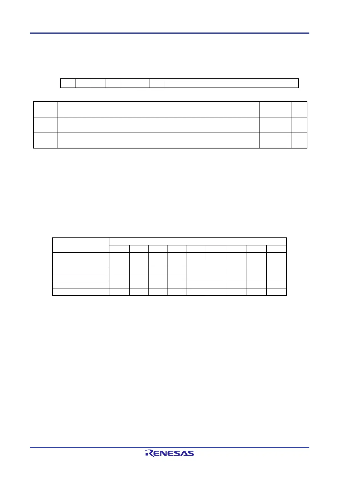
(24) UART Transmission Data Register (LUTDRn)
Address: F06E5H, F06E4H
15 14 13 12 11 10 9 8 7 6 5 4 3 2 1 0
— — — — — — — [8:0]
Value after reset:
0 0 0 0 0 0 0 0 0 0 0 0 0 0 0 0
Bit Function
Setting
Range
R/W
8 to 0 Sets the data to be transmitted from the transmission buffer. 000H to
1FFH
R/W
15 to 9 Reserved.
These bits are always read as 0. The write value should always be 0.
— R/W
The LUTDRn register sets the data to be transmitted from the transmission data register.
Writing data to this register with the UTOE bit in the LUOERn register set to 1 starts transmission.
This register can be accessed in 8 bits.
In 9-bit communication mode, do not attempt 8-bit access.
Do not write data to this register when data transmission from the UART buffer is in progress.
Also, do not write data to this register when a transmission request is being generated due to write access to the LUWTDRn
register.
When transmitting multiple sets of data continuously, do not write another data item to this register before a transmission
interrupt is generated.
The table below shows the bit arrangement according to the set transfer format.
Item
LUTDRn
8 7 6 5 4 3 2 1 0
7-bit; LSB first — — Bit 6 Bit 5 Bit 4 Bit 3 Bit 2 Bit 1 Bit 0
7-bit; MSB first — — Bit 0 Bit 1 Bit 2 Bit 3 Bit 4 Bit 5 Bit 6
8-bit; LSB first — Bit 7 Bit 6 Bit 5 Bit 4 Bit 3 Bit 2 Bit 1 Bit 0
8-bit; MSB first — Bit 0 Bit 1 Bit 2 Bit 3 Bit 4 Bit 5 Bit 6 Bit 7
9-bit; LSB first Bit 8 Bit 7 Bit 6 Bit 5 Bit 4 Bit 3 Bit 2 Bit 1 Bit 0
9-bit; MSB first Bit 0 Bit 1 Bit 2 Bit 3 Bit 4 Bit 5 Bit 6 Bit 7 Bit 8

 Loading...


