RL78/F13, F14 CHAPTER 17 LIN/UART MODULE (RLIN3)
R01UH0368EJ0210 Rev.2.10 1203
Dec 10, 2015
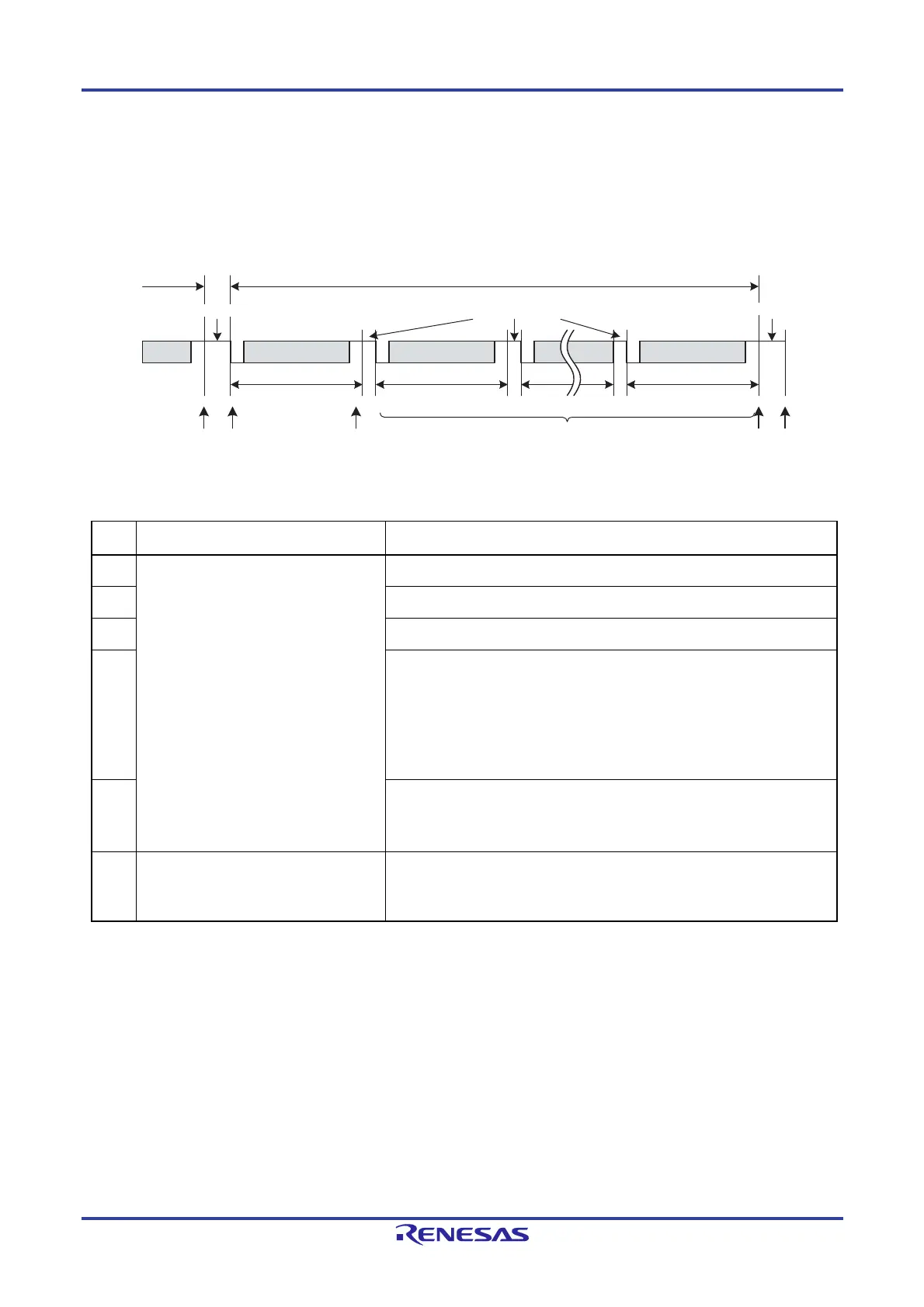
(c) Response Reception
Figure 17-7 shows the operation of the LIN/UART module (LIN master mode) on response reception. Table 17-
9 provides processing in response reception.
Figure 17-7. Operation in Response Reception
Table 17-9.
Processing in Response Reception
Step Software processing LIN/UART module processing
(1) Waits for an interrupt request (no
processing).
Waits for detection of a start bit.
(2) Receives the data 1 when the start bit is detected.
(3) Sets the successful data 1 reception flag.
(4)
Receives the data 2 when the start bit is detected.
Receives the data 3 when the start bit is detected.
Repeats the transmission of inter-byte spaces as many times as the data
length specified in bits RFDL[3:0] in the LDFCn register, and stops the
transmission when any bit in the LESTn register is 1 (bit error detected). If an
error occurs, the checksum determination in item (5) is not performed).
:
Receives the checksum when the start bit is detected.
(5)
Determines the checksum.
Sets the successful frame/wake-up reception flag.
Sets the FTS bit in the LTRCn register to 0 (frame transmission or wake-up
transmission/reception stopped).
(6)
Processing after communication
Reads the received data.
Checks the LSTn register and clears
flags.
Idle
For information about error detection, refer to 17.4.6 Error Status.
Interrupt
Header
ID +
parity
Response space
Response
Data 1
Data field
Data 2
Data field
Inter-byte space
Checksum
Checksum
(1) (2) (3) (5)(4) (6)
Inter-frame space
 Loading...


