RL78/F13, F14 CHAPTER 17 LIN/UART MODULE (RLIN3)
R01UH0368EJ0210 Rev.2.10 1205
Dec 10, 2015
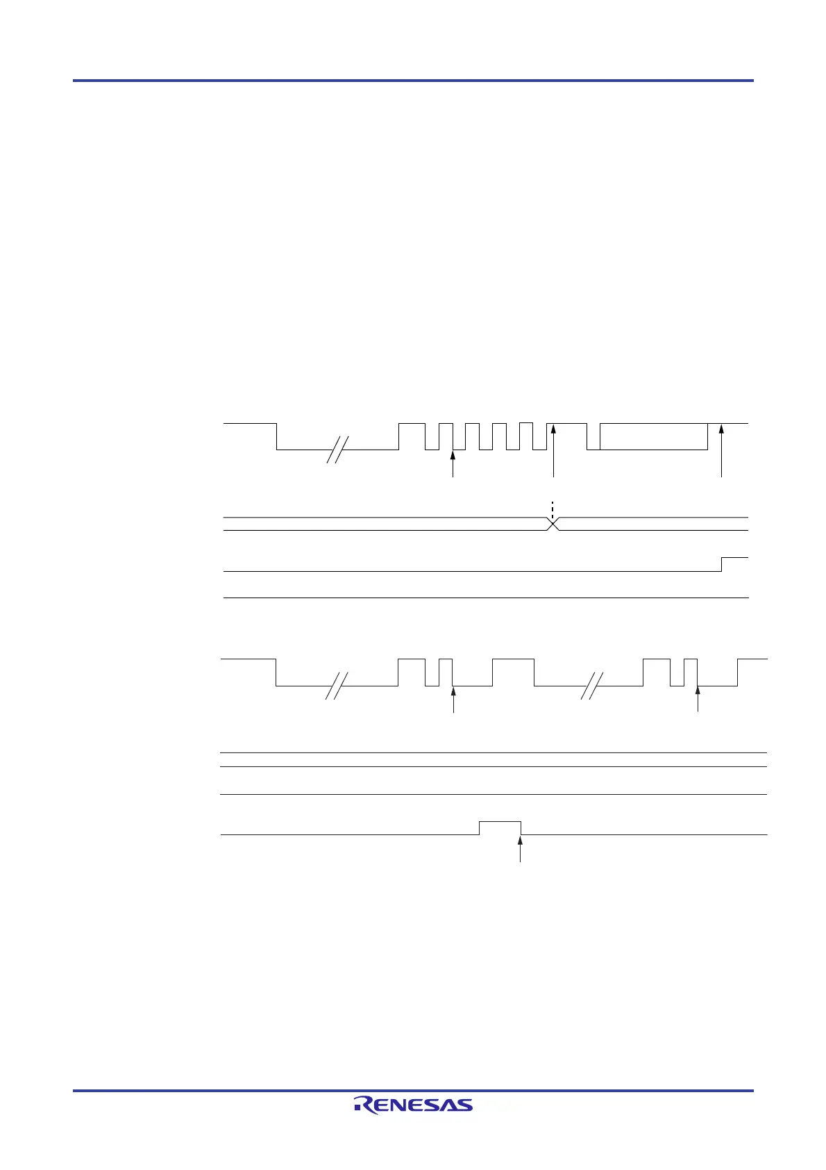
(1) Auto Baud Rate Correction Function
In LIN slave mode [auto baud rate], the system always measures the low-level widths that are received. If the first “Low”
width is 10 times (if the BLT bit in the LBFCn register is “0”) or 11 times (if the BLT bit in the LBFCn register is “1”) or greater
calculated from the average of the starting 2 bits (the period of the consecutive fall edges from the beginning of the sync
field) of the sync field, the system concludes that the detection of a break field was successful, and verifies that the data in
the sync field is 55H. When confirming that the data is 55H and the reception of the sync field is successful, the system
automatically sets the baud rate correction results in the LBRPn1 and LBRPn0 registers.
If data is received up to the ID field without error, a successful header reception interrupt is generated at the stop bit position.
If the sync field data is not 55H, the system concludes that the detection of a sync field failed, and sets a sync field error
flag, and generates an error detection interrupt.
In such a case, the LIN/UART module waits for the detection of another break field (“Low”) without baud rate correction.
Figure 17-9. Header Reception in LIN Slave Mode [Auto Baud Rate] (in Normal Operation)
Figure 17-10. Header Reception in LIN Slave Mode [Auto Baud Rate] (Sync Field Error)
LRXDn
LBRPn0 register
LBRPn1 register
HTRC bit in LSTn register
Break detection
successful
Sync field detection
successful
Header reception
successful
New value after synchronization
ID + parity
SFER bit in LESTn register
Value before synchronization
LRXDn
Cleared by software
LBRPn0 register
LBRPn1 register
HTRC bit in LSTn register
Value before synchronization
Break detection
successful
SFER bit in LESTn register
Break detection
successful
 Loading...


