Real-time clock (RTC) RM0351
1210/1830 DocID024597 Rev 5
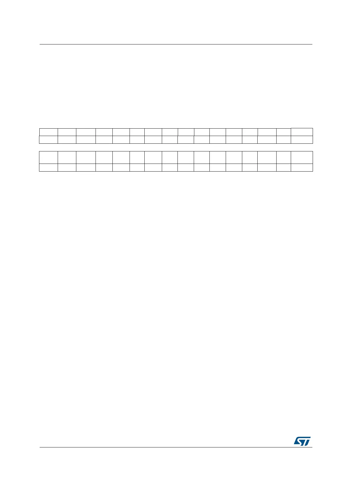
38.6.4 RTC initialization and status register (RTC_ISR)
This register is write protected (except for RTC_ISR[13:8] bits). The write access procedure
is described in RTC register write protection on page 1193.
Address offset: 0x0C
Backup domain reset value: 0x0000 0007
System reset: not affected except INIT, INITF, and RSF bits which are cleared to ‘0’
31 30 29 28 27 26 25 24 23 22 21 20 19 18 17 16
Res. Res. Res. Res. Res. Res. Res. Res. Res. Res. Res. Res. Res. Res. ITSF RECALPF
rc_w0 r
15 14 13 12 11 10 9 8 7 6 5 4 3 2 1 0
TAMP3F TAMP2F TAMP1F TSOVF TSF WUTF ALRBF ALRAF INIT INITF RSF INITS SHPF WUTWF
ALRB
WF
ALRAWF
rc_w0 rc_w0 rc_w0 rc_w0 rc_w0 rc_w0 rc_w0 rc_w0 rw r rc_w0 r r r r r
Bits 31:18 Reserved, must be kept at reset value
Bit 17 ITSF: Internal tTime-stamp flag
This flag is set by hardware when a time-stamp on the internal event occurs.
This flag is cleared by software by writing 0, and must be cleared together with TSF bit by
writing 0 in both bits.
Bit 16 RECALPF: Recalibration pending Flag
The RECALPF status flag is automatically set to ‘1’ when software writes to the RTC_CALR
register, indicating that the RTC_CALR register is blocked. When the new calibration settings
are taken into account, this bit returns to ‘0’. Refer to Re-calibration on-the-fly.
Bit 15 TAMP3F: RTC_TAMP3 detection flag
This flag is set by hardware when a tamper detection event is detected on the RTC_TAMP3
input.
It is cleared by software writing 0
Bit 14 TAMP2F: RTC_TAMP2 detection flag
This flag is set by hardware when a tamper detection event is detected on the RTC_TAMP2
input.
It is cleared by software writing 0
Bit 13 TAMP1F: RTC_TAMP1 detection flag
This flag is set by hardware when a tamper detection event is detected on the RTC_TAMP1
input.
It is cleared by software writing 0
Bit 12 TSOVF: Time-stamp overflow flag
This flag is set by hardware when a time-stamp event occurs while TSF is already set.
This flag is cleared by software by writing 0. It is recommended to check and then clear
TSOVF only after clearing the TSF bit. Otherwise, an overflow might not be noticed if a time-
stamp event occurs immediately before the TSF bit is cleared.
Bit 11 TSF: Time-stamp flag
This flag is set by hardware when a time-stamp event occurs.
This flag is cleared by software by writing 0. If ITSF flag is set, TSF must be cleared together
with ITSF by writing 0 in both bits.
 Loading...


