DocID024597 Rev 5 625/1830
RM0351 Digital-to-analog converter (DAC)
647
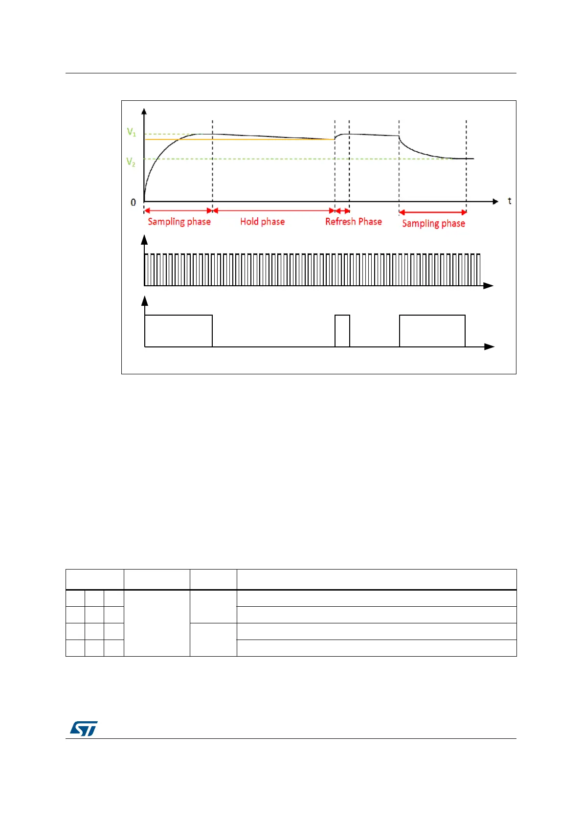
Figure 145. DAC sample and hold mode phase diagram
Like in normal mode, the sample and hold mode has different configurations.
To enable the output buffer, the MODEx[2:0] bits in DAC_MCR register should be:
• 100: DAC is connected to the external pin
• 101: DAC is connected to external pin and to on chip peripherals
To disabled the output buffer, The MODEx[2:0] bits in DAC_MCR register should be:
• 110: DAC is connected to external pin and to on chip peripherals
• 111: DAC is connected to on chip peripherals
When MODEx[2:0] bits in DAC_MCR register is equal to 111. An internal capacitor “C
loadint“
will hold the voltage output of the DAC Core and then drive it to on-chip peripherals.
All sample and hold phases are interruptible and any change in DAC_DHRx will trigger
immediately a new sample phase.
Table 124. Channel output modes summary
MODEx[2:0] Mode Buffer Output connections
000
Normal mode
Enabled
Connected to external pin
0 0 1 Connected to external pin and to on chip-peripherals (ex, comparators)
010
Disabled
Connected to external pin
0 1 1 Connected to on chip peripherals (ex, comparators)
 Loading...


