DocID024597 Rev 5 649/1830
RM0351 Digital camera interface (DCMI)
671
The data flow is synchronized either by hardware using the optional DCMI_HSYNC
(horizontal synchronization) and DCMI_VSYNC (vertical synchronization) signals or by
synchronization codes embedded in the data flow.
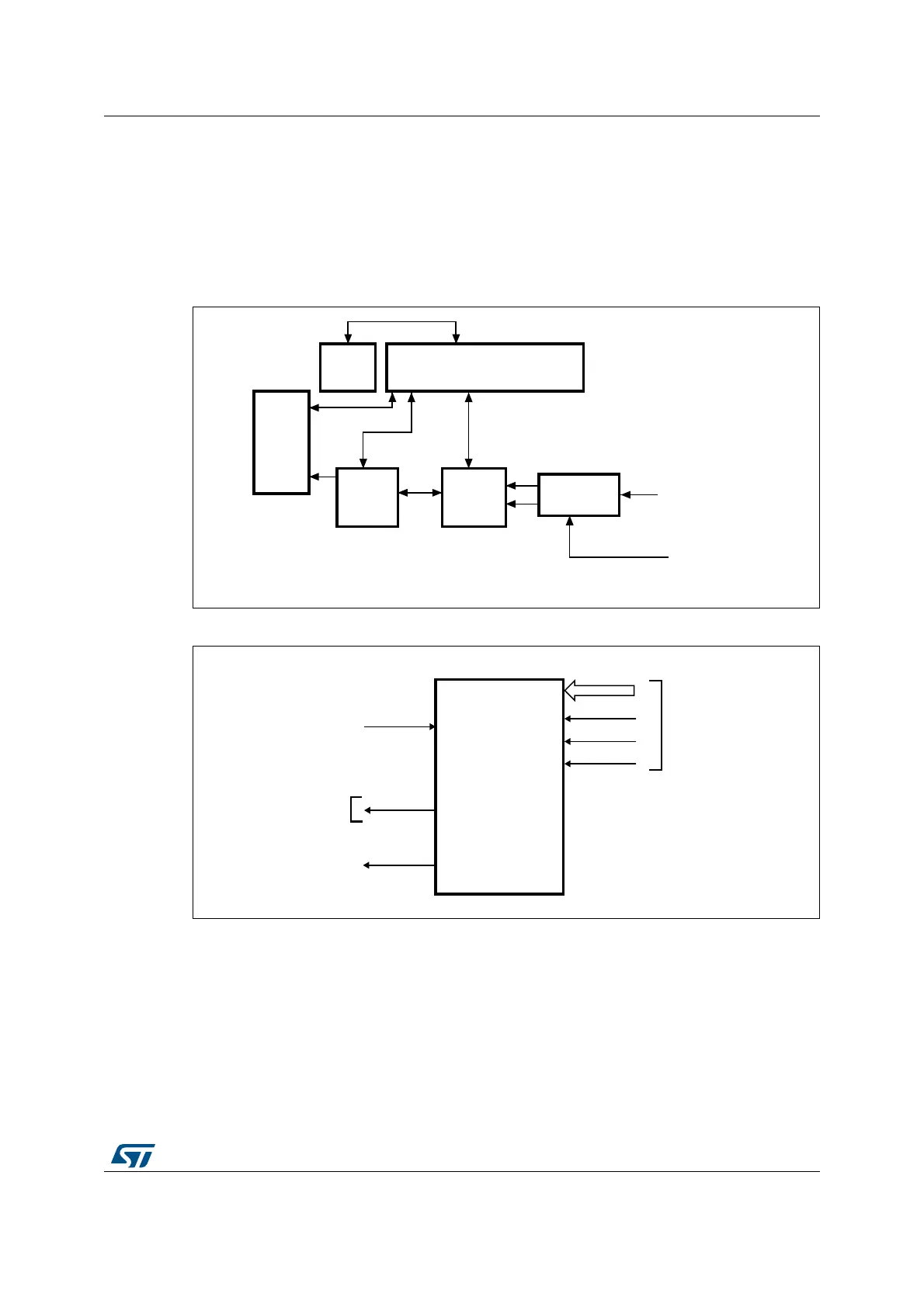
20.4.1 DCMI block diagram
Figure 146 shows the DCMI block diagram.
Figure 146.DCMI block diagram
Figure 147.Top-level block diagram
20.4.2 DMA interface
The DMA interface is active when the CAPTURE bit in the DCMI_CR register is set. A DMA
request is generated each time the camera interface receives a complete 32-bit data block
in its register.
20.4.3 DCMI physical interface
The interface is composed of 11/13/15/17 inputs. Only the Slave mode is supported.
'0$
LQWHUIDFH
&RQWURO6WDWXV
UHJLVWHU
$+%
LQWHUIDFH
),)2
'DWD
IRUPDWWHU
'DWD
H[WUDFWLRQ
6\QFKURQL]HU
'&0,B3,;&/.
'&0,B'>@'&0,B+6<1&'&0,B96<1&
DLE
$#-)
)NTERRUPT
CONTROLLER
$#-)?)4
%XTERNAL
INTERFACE
$#-)?$;=
$#-)?0)8#,+
$#-)?(39.#
$#-)?639.#
$-!?2%1
(#,+
AIB
 Loading...


