Power control (PWR) RM0351
166/1830 DocID024597 Rev 5
Debug mode
By default, the debug connection is lost if the application puts the MCU in Stop 0, Stop1,
Stop 2, Standby or Shutdown mode while the debug features are used. This is due to the
fact that the Cortex
®
-M4 core is no longer clocked.
However, by setting some configuration bits in the DBGMCU_CR register, the software can
be debugged even when using the low-power modes extensively. For more details, refer to
Section 48.16.1: Debug support for low-power modes.
5.3.1 Run mode
Slowing down system clocks
In Run mode, the speed of the system clocks (SYSCLK, HCLK, PCLK) can be reduced by
programming the prescaler registers. These prescalers can also be used to slow down the
peripherals before entering the Sleep mode.
For more details, refer to Section 6.4.3: Clock configuration register (RCC_CFGR).
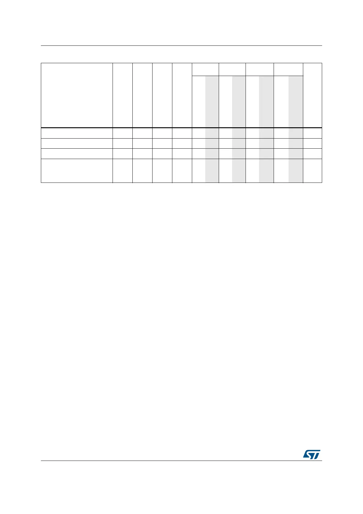
AES hardware accelerator O O O O - ---- ----
HASH hardware accelerator O O O O -
---- ----
CRC calculation unit O O O O -
---- ----
GPIOs O O O O O
OOO
(9)
5
pins
(10)
(11)
5
pins
(10)
-
1. Legend: Y = Yes (Enable). O = Optional (Disable by default. Can be enabled by software). - = Not available.
2. The Flash can be configured in power-down mode. By default, it is not in power-down mode.
3. The SRAM clock can be gated on or off.
4. SRAM2 content is preserved when the bit RRS is set in PWR_CR3 register.
5. Some peripherals with wakeup from Stop capability can request HSI16 to be enabled. In this case, HSI16 is woken up by
the peripheral, and only feeds the peripheral which requested it. HSI16 is automatically put off when the peripheral does not
need it anymore.
6. UART and LPUART reception is functional in Stop mode, and generates a wakeup interrupt on Start, address match or
received frame event.
7. I2C address detection is functional in Stop mode, and generates a wakeup interrupt in case of address match.
8. Voltage scaling Range 1, SMPS Range 1 or SMPS Range 2 High only.
9. I/Os can be configured with internal pull-up, pull-down or floating in Standby mode.
10. The I/Os with wakeup from Standby/Shutdown capability are: PA0, PC13, PE6, PA2, PC5.
11. I/Os can be configured with internal pull-up, pull-down or floating in Shutdown mode but the configuration is lost when
exiting the Shutdown mode.
Table 23. Functionalities depending on the working mode
(1)
(continued)
Peripheral Run Sleep
Low-power run
Low-power sleep
Stop 0/1 Stop 2 Standby Shutdown
VBAT
-
Wakeup capability
-
Wakeup capability
-
Wakeup capability
-
Wakeup capability
 Loading...


