DocID024597 Rev 5 1417/1830
RM0351 Serial peripheral interface (SPI)
1446
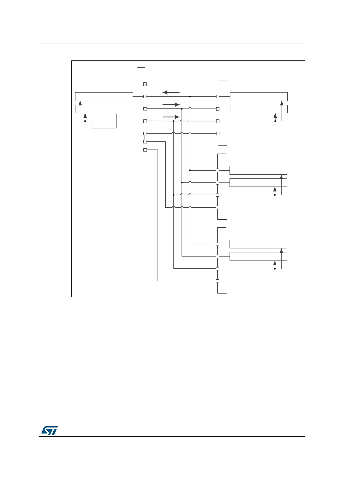
Figure 447. Master and three independent slaves
1. NSS pin is not used on master side at this configuration. It has to be managed internally (SSM=1, SSI=1) to
prevent any MODF error.
2. As MISO pins of the slaves are connected together, all slaves must have the GPIO configuration of their
MISO pin set as alternate function open-drain (see Section 8.3.7: I/O alternate function input/output on
page 295.
42.4.4 Multi-master communication
Unless SPI bus is not designed for a multi-master capability primarily, the user can use build
in feature which detects a potential conflict between two nodes trying to master the bus at
the same time. For this detection, NSS pin is used configured at hardware input mode.
The connection of more than two SPI nodes working at this mode is impossible as only one
node can apply its output on a common data line at time.
When nodes are non active, both stay at slave mode by default. Once one node wants to
overtake control on the bus, it switches itself into master mode and applies active level on
the slave select input of the other node via dedicated GPIO pin. After the session is
5[VKLIWUHJLVWHU
7[VKLIWUHJLVWHU 5[VKLIWUHJLVWHU
7[VKLIWUHJLVWHU
63,FORFN
JHQHUDWRU
0DVWHU
6ODYH
0,62
026,
6&.
166
0,62
026,
6&.
166
5[VKLIWUHJLVWHU
7[VKLIWUHJLVWHU
6ODYH
5[VKLIWUHJLVWHU
7[VKLIWUHJLVWHU
6ODYH
,2
,2
,2
0,62
026,
6&.
166
0,62
026,
6&.
166
06Y9
 Loading...


