DocID024597 Rev 5 527/1830
RM0351 Analog-to-digital converters (ADC)
614
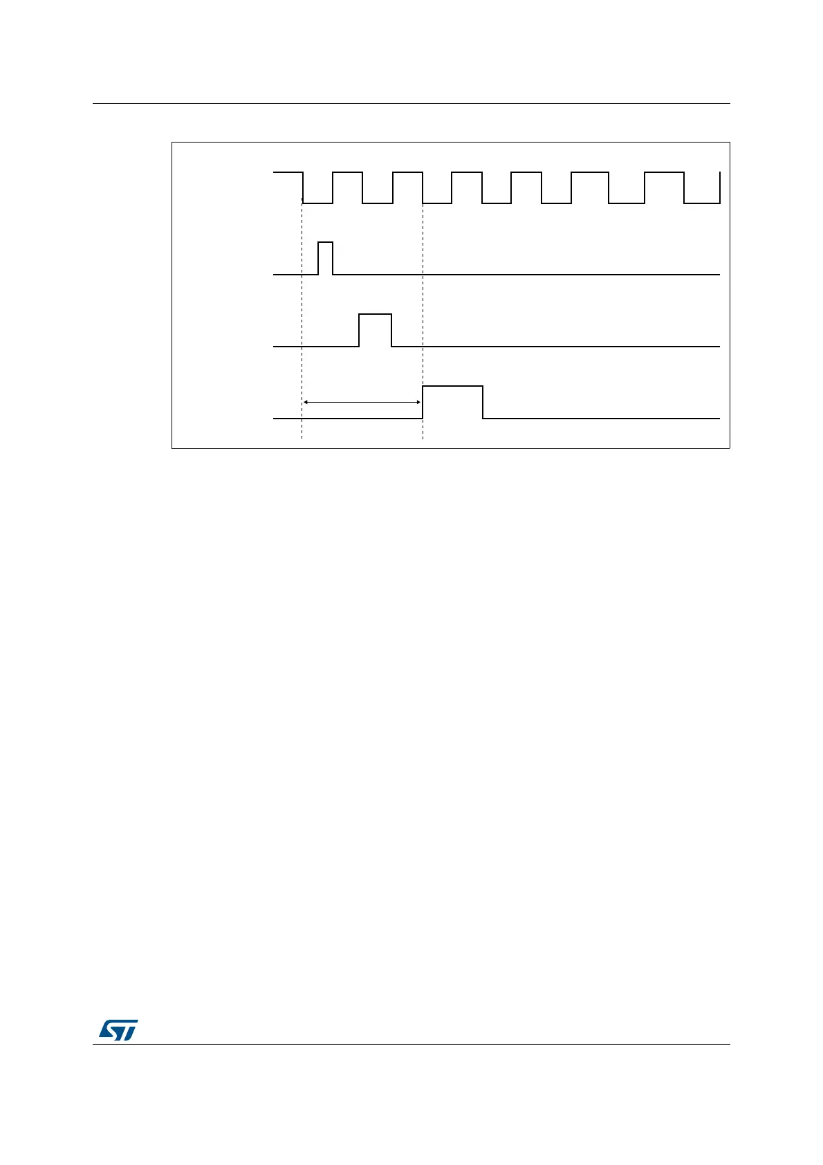
Figure 79. Injected conversion latency
1. The maximum latency value can be found in the electrical characteristics of the STM32L4x5/STM32L4x6
datasheet.
18.4.20 Discontinuous mode (DISCEN, DISCNUM, JDISCEN)
Regular group mode
This mode is enabled by setting the DISCEN bit in the ADC_CFGR register.
It is used to convert a short sequence (sub-group) of n conversions (n 8) that is part of the
sequence of conversions selected in the ADC_SQR registers. The value of n is specified by
writing to the DISCNUM[2:0] bits in the ADC_CFGR register.
When an external trigger occurs, it starts the next n conversions selected in the ADC_SQR
registers until all the conversions in the sequence are done. The total sequence length is
defined by the L[3:0] bits in the ADC_SQR1 register.
Example:
• DISCEN=1, n=3, channels to be converted = 1, 2, 3, 6, 7, 8, 9, 10, 11
– 1st trigger: channels converted are 1, 2, 3 (an EOC event is generated at each
conversion).
– 2nd trigger: channels converted are 6, 7, 8 (an EOC event is generated at each
conversion).
– 3rd trigger: channels converted are 9, 10, 11 (an EOC event is generated at each
conversion) and an EOS event is generated after the conversion of channel 11.
– 4th trigger: channels converted are 1, 2, 3 (an EOC event is generated at each
conversion).
!$##,+
AIB
,QMHFWLRQHYHQW
5HVHW$'&
62&
PD[ODWHQF\
 Loading...


