DocID024597 Rev 5 335/1830
RM0351 Direct memory access controller (DMA)
356
11.4 DMA functional description
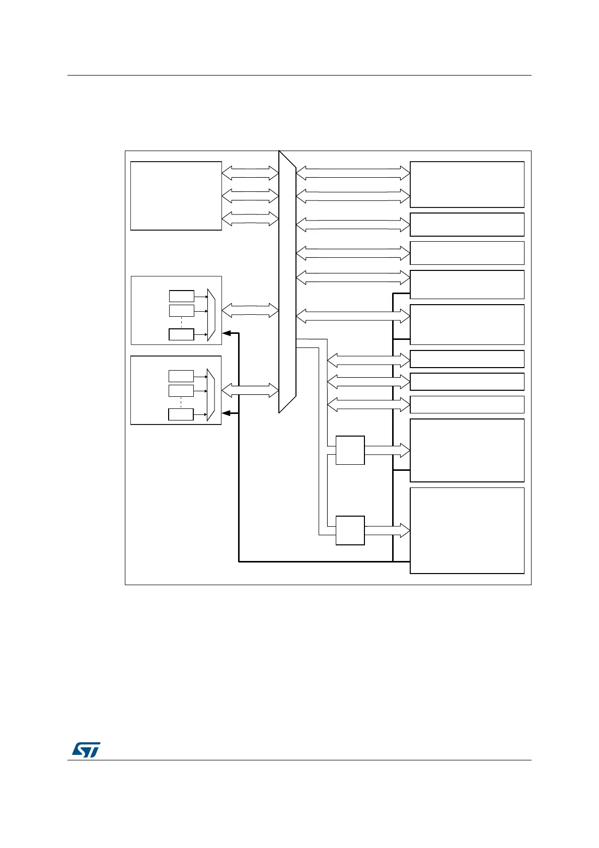
The block diagram is shown in the following figure.
Figure 29. DMA block diagram
The DMA controller performs direct memory transfer by sharing the system bus with the
Cortex
®
-M4 core. The DMA request may stop the CPU access to the system bus for some
bus cycles, when the CPU and DMA are targeting the same destination (memory or
peripheral). The bus matrix implements round-robin scheduling, thus ensuring at least half
of the system bus bandwidth (both to memory and peripheral) for the CPU.
11.4.1 DMA transactions
After an event, the peripheral sends a request signal to the DMA Controller. The DMA
controller serves the request depending on the channel priorities. As soon as the DMA
Controller accesses the peripheral, an Acknowledge is sent to the peripheral by the DMA
06Y9
65$0
&K
&K
&K
'0$
'0$UHTXHVWV
5HVHWFORFNFRQWURO5&&
&RUWH[
0ZLWK)38
)ODVKLQWHUIDFH
$3%SHULSKHUDOV
ZLWK'0$FDSDELOLW\
')6'06$,6$,7,0
7,07,07,07,0
86$5763,6'00&
$3%SHULSKHUDOV
ZLWK'0$FDSDELOLW\
6:30,/38$57'$&
'$&,&,&,&,&
86$5786$578$57
8$5763,63,7,0
7,07,07,07,07,0
)0&DQG4XDG63,
$+%SHULSKHUDOV
ZLWK'0$FDSDELOLW\
$(6+$6+'&0,
$'&$'&$'&
&5&
6EXV
'EXV
,EXV
76&
65$0
$+%
%ULGJH
$3%
$3%
,&RGH
'&RGH
%ULGJH
'0$
&K
&K
&K
'0$
%XVPDWUL[
'0$
 Loading...


