DocID024597 Rev 5 503/1830
RM0351 Analog-to-digital converters (ADC)
614
– DAC1 and DAC2 internal channels, connected to ADC2 and ADC3
• Start-of-conversion can be initiated:
– by software for both regular and injected conversions
– by hardware triggers with configurable polarity (internal timers events or GPIO
input events) for both regular and injected conversions
• Conversion modes
– Each ADC can convert a single channel or can scan a sequence of channels
– Single mode converts selected inputs once per trigger
– Continuous mode converts selected inputs continuously
– Discontinuous mode
• Dual ADC mode for ADC1 and 2
• Interrupt generation at ADC ready, the end of sampling, the end of conversion (regular
or injected), end of sequence conversion (regular or injected), analog watchdog 1, 2 or
3 or overrun events
• 3 analog watchdogs per ADC
• ADC supply requirements: 1.62 to 3.6 V
• ADC input range: V
REF–
V
IN
V
REF+
Figure 66 shows the block diagram of one ADC.
18.3 ADC implementation
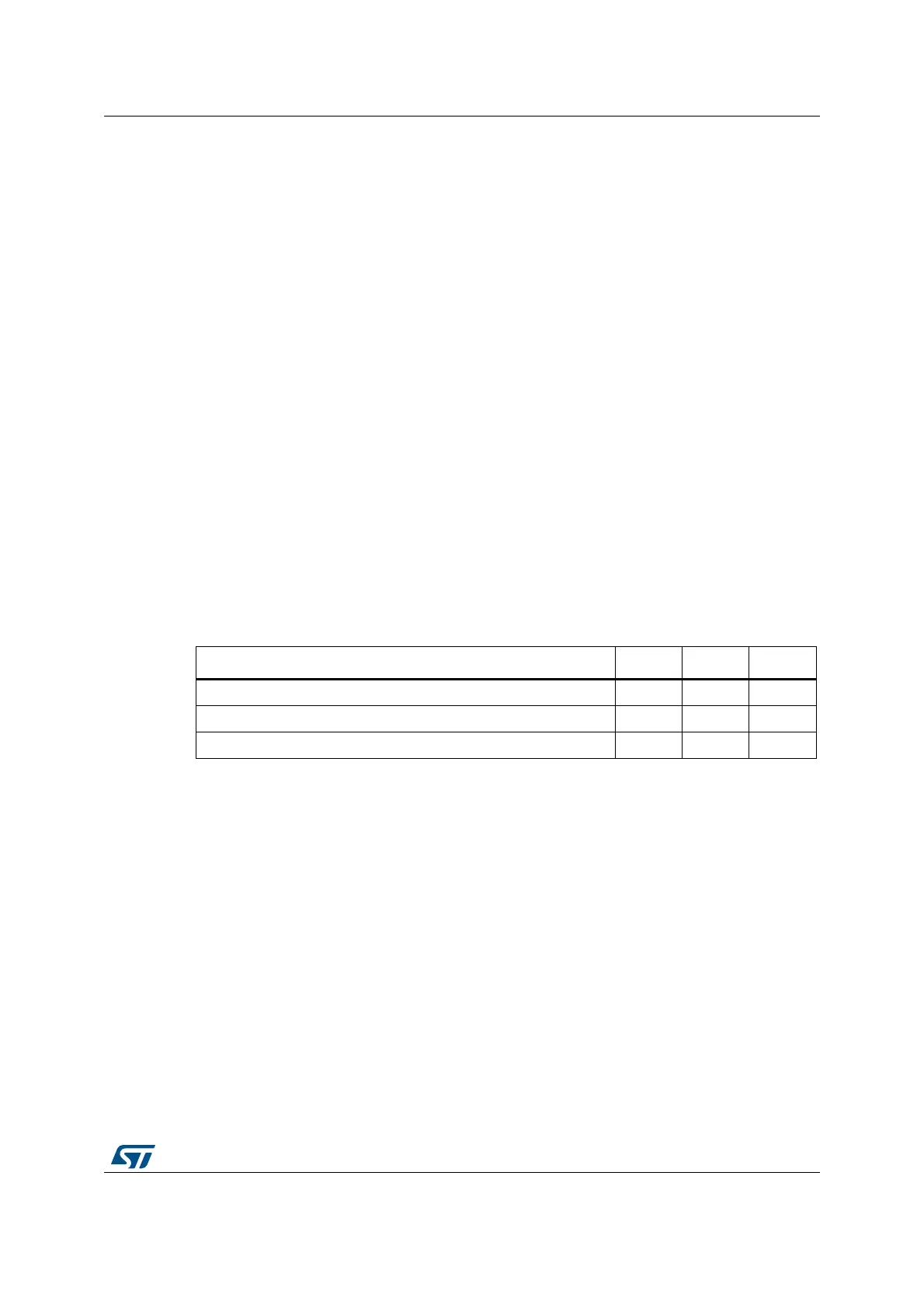
Table 102. Main ADC features
References ADC1 ADC2 ADC3
Dual mode XXX
DFSDM interface
(1)
1. Available only on STM32L496xx/STM32L4A6xx.
XXX
SMPPLUS control
(1)
XXX

 Loading...