DocID024597 Rev 5 1269/1830
RM0351 Inter-integrated circuit (I2C) interface
1301
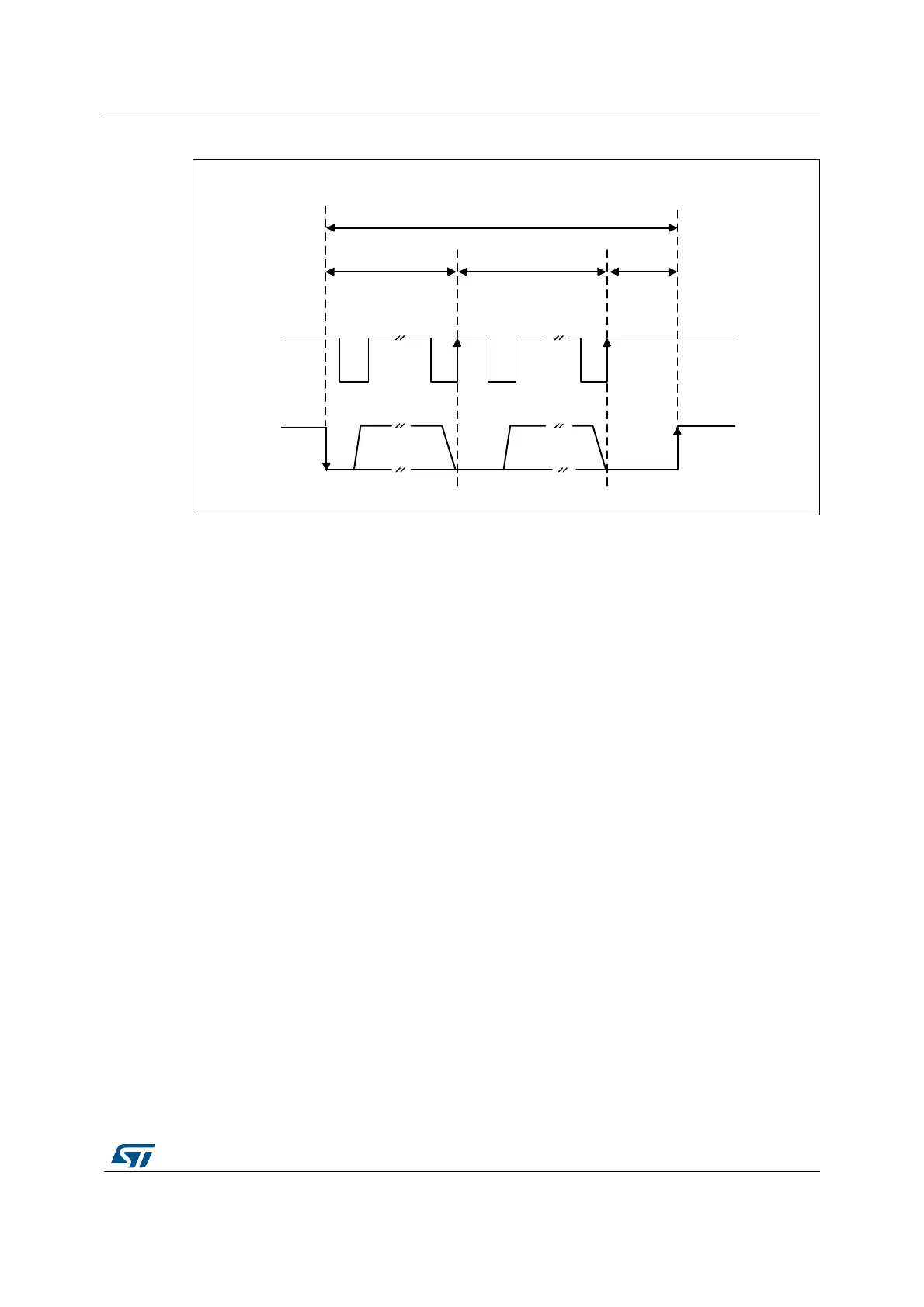
Figure 398. Timeout intervals for t
LOW:SEXT
, t
LOW:MEXT
.
Bus idle detection
A master can assume that the bus is free if it detects that the clock and data signals have
been high for t
IDLE
greater than t
HIGH
,
MAX
. (refer to Table 220: I2C-SMBUS specification clock
timings)
This timing parameter covers the condition where a master has been dynamically added to
the bus and may not have detected a state transition on the SMBCLK or SMBDAT lines. In
this case, the master must wait long enough to ensure that a transfer is not currently in
progress. The peripheral supports a hardware bus idle detection.
39.4.11 SMBus initialization
This section is relevant only when SMBus feature is supported. Please refer to Section 39.3:
I2C implementation.
In addition to I2C initialization, some other specific initialization must be done in order to
perform SMBus communication:
Received Command and Data Acknowledge control (Slave mode)
A SMBus receiver must be able to NACK each received command or data. In order to allow
ACK control in slave mode, the Slave Byte Control mode must be enabled by setting the
SBC bit in the I2C_CR1 register. Refer to Slave Byte Control mode on page 1246 for more
details.
069
6WDUW 6WRS
W
/2:6(;7
W
/2:0(;7
W
/2:0(;7
W
/2:0(;7
&ON
$FN
&ON
$FN
60%&/.
60%'$7
 Loading...


