DocID024597 Rev 5 539/1830
RM0351 Analog-to-digital converters (ADC)
614
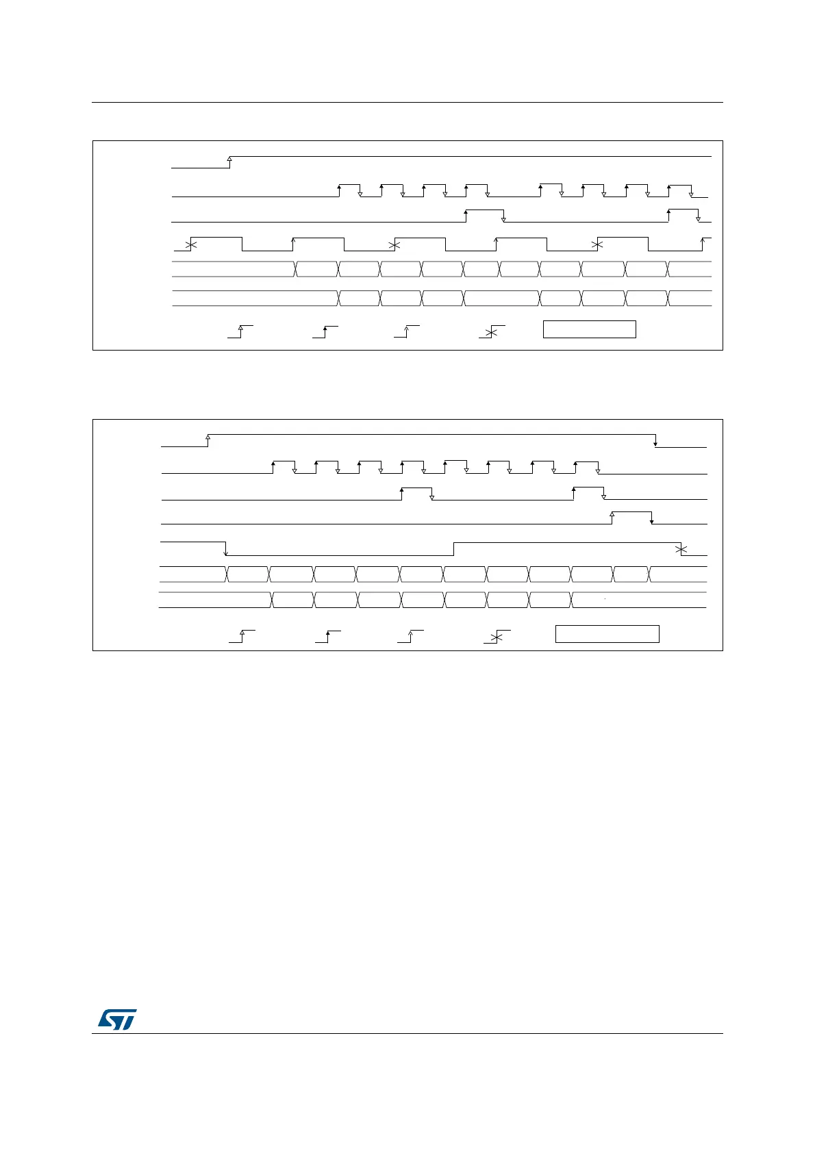
Figure 94. Single conversions of a sequence, hardware trigger
1. TRGx (over-frequency) is selected as trigger source, EXTEN = 01, CONT = 0
2. Channels selected = 1, 2, 3, 4; AUTDLY=0.
Figure 95. Continuous conversions of a sequence, hardware trigger
1. TRGx is selected as trigger source, EXTEN = 10, CONT = 1
2. Channels selected = 1, 2, 3, 4; AUTDLY=0.
18.4.26 Data management
Data register, data alignment and offset (ADC_DR, OFFSETy, OFFSETy_CH,
ALIGN)
Data and alignment
At the end of each regular conversion channel (when EOC event occurs), the result of the
converted data is stored into the ADC_DR data register which is 16 bits wide.
At the end of each injected conversion channel (when JEOC event occurs), the result of the
converted data is stored into the corresponding ADC_JDRy data register which is 16 bits
wide.
The ALIGN bit in the ADC_CFGR register selects the alignment of the data stored after
conversion. Data can be right- or left-aligned as shown in Figure 96, Figure 97, Figure 98
069
(2&
(26
75*;
$'&B'5
5'<
&+ &+
5($'<
&+ &+ &+ &+ &+ &+ 5'<
' ' ' ' ''
E\VZ E\KZ
' '
WULJJHUHG LJQRUHG
$'67$57
$'&VWDWH
,QGLFDWLYHWLPLQJV
069
(2&
(26
75*[
$'&B'5
5'< &+ &+
&+
&+ &+ &+ &+ &+ &+
5'<
' ' ' ' ''
E\VZ E\KZ
1RWLQVFDOHWLPLQJV
' '
WULJJHUHG LJQRUHG
6723
$'673
$'67$57
$'&
 Loading...


