Advanced-control timers (TIM1/TIM8) RM0351
920/1830 DocID024597 Rev 5
30.3.18 Clearing the OCxREF signal on an external event
When ETRF is chosen, ETR must be configured as follows:
1. The External Trigger Prescaler should be kept off: bits ETPS[1:0] of the TIMx_SMCR
register set to ‘00’.
2. The external clock mode 2 must be disabled: bit ECE of the TIMx_SMCR register set to
‘0’.
3. The External Trigger Polarity (ETP) and the External Trigger Filter (ETF) can be
configured according to the user needs.
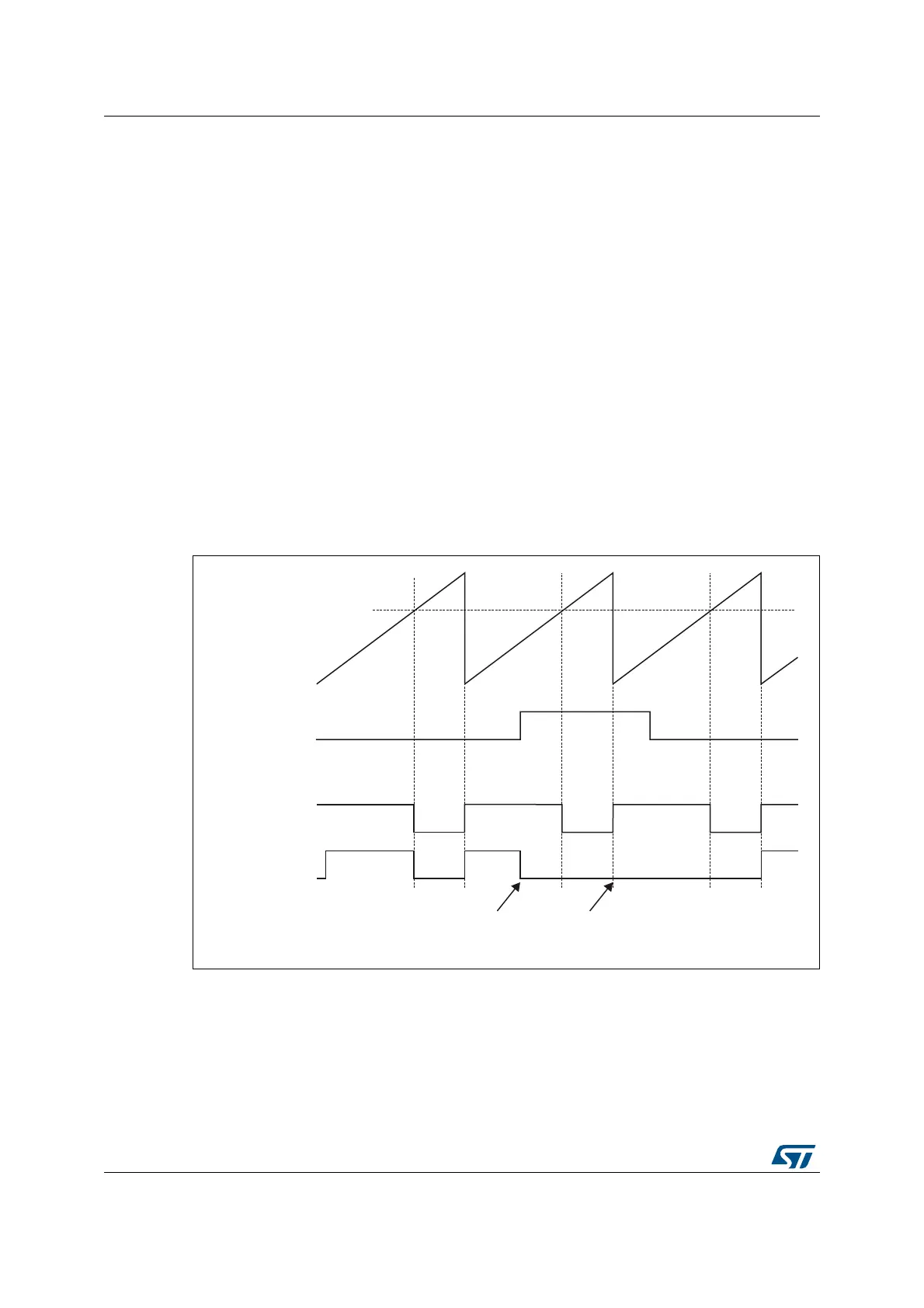
Figure 260 shows the behavior of the OCxREF signal when the ETRF Input becomes High,
for both values of the enable bit OCxCE. In this example, the timer TIMx is programmed in
PWM mode.
Figure 260. Clearing TIMx OCxREF
Note: In case of a PWM with a 100% duty cycle (if CCRx>ARR), then OCxREF is enabled again at
the next counter overflow.
The OCxREF signal of a given channel can be cleared when a high level is applied on the
ocref_clr_int input (OCxCE enable bit in the corresponding TIMx_CCMRx register set to 1).
OCxREF remains low until the next update event (UEV) occurs. This function can only be
used in Output compare and PWM modes. It does not work in Forced mode. The
OCREF_CLR input is not connected (NC) in this product. The OCCS bit must be set to work
in OCxREF clearing mode.
069
&&5[
&RXQWHU&17
(75)
2&[5()
2&[&( µ
2&[5()
2&[&( µ
RFUHIBFOUBLQW
EHFRPHVKLJK
RFUHIBFOUBLQW
VWLOOKLJK
 Loading...


