Inter-integrated circuit (I2C) interface RM0351
1284/1830 DocID024597 Rev 5
Depending on the product implementation, all these interrupts events can either share the
same interrupt vector (I2C global interrupt), or be grouped into 2 interrupt vectors (I2C event
interrupt and I2C error interrupt). Refer to
Table 57: STM32L4x5/STM32L4x6 vector table for
details.
In order to enable the I2C interrupts, the following sequence is required:
1. Configure and enable the I2C IRQ channel in the NVIC.
2. Configure the I2C to generate interrupts.
The I2C wakeup event is connected to the EXTI controller (refer to Section 14: Extended
interrupts and events controller (EXTI)).
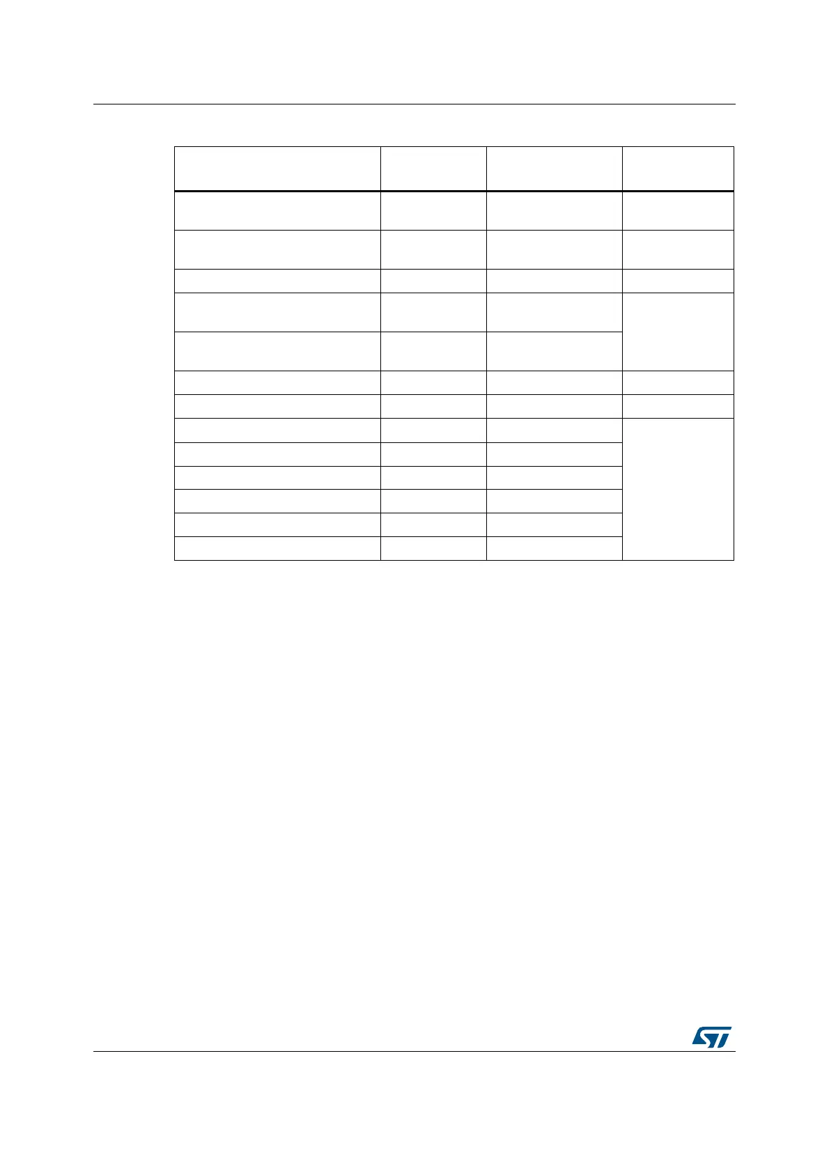
Table 230. I2C Interrupt requests
Interrupt event Event flag
Event flag/Interrupt
clearing method
Interrupt enable
control bit
Receive buffer not empty RXNE
Read I2C_RXDR
register
RXIE
Transmit buffer interrupt status TXIS
Write I2C_TXDR
register
TXIE
Stop detection interrupt flag STOPF Write STOPCF=1 STOPIE
Transfer Complete Reload TCR
Write I2C_CR2 with
NBYTES[7:0]
0
TCIE
Transfer complete TC
Write START=1 or
STOP=1
Address matched ADDR Write ADDRCF=1 ADDRIE
NACK reception NACKF Write NACKCF=1 NACKIE
Bus error BERR Write BERRCF=1
ERRIE
Arbitration loss ARLO Write ARLOCF=1
Overrun/Underrun OVR Write OVRCF=1
PEC error PECERR Write PECERRCF=1
Timeout/t
LOW
error TIMEOUT Write TIMEOUTCF=1
SMBus Alert ALERT Write ALERTCF=1
 Loading...


