DocID024597 Rev 5 1329/1830
RM0351 Universal synchronous asynchronous receiver transmitter (USART)
1411
Note: The CK pin works in conjunction with the TX pin. Thus, the clock is provided only if the
transmitter is enabled (TE=1) and data is being transmitted (the data register USART_TDR
written). This means that it is not possible to receive synchronous data without transmitting
data.
The LBCL, CPOL and CPHA bits have to be selected when the USART is disabled (UE=0)
to ensure that the clock pulses function correctly.
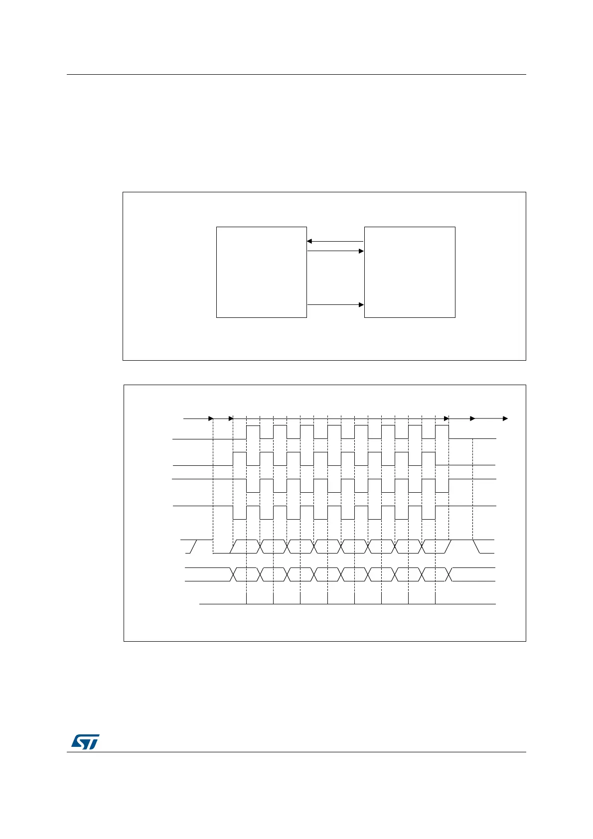
Figure 417. USART example of synchronous transmission
Figure 418. USART data clock timing diagram (M bits = 00)
06Y9
86$57
6\QFKURQRXVGHYLFH
HJVODYH63,
5;
7;
'DWDRXW
'DWDLQ
&ORFN
&.
06Y9
06%
06%
/6%
/6%
6WDUW
6WDUW 6WRS
,GOHRUSUHFHGLQJ
WUDQVPLVVLRQ
,GOHRUQH[W
WUDQVPLVVLRQ
/%&/ELWFRQWUROVODVWGDWDSXOVH
&DSWXUHVWUREH
'DWDRQ5;
IURPVODYH
'DWDRQ7;
IURPPDVWHU
&ORFN&32/ &3+$
&ORFN&32/ &3+$
&ORFN&32/ &3+$
&ORFN&32/ &3+$
6WRS
0ELWV
 Loading...


