DocID024597 Rev 5 1021/1830
RM0351 General-purpose timers (TIM2/TIM3/TIM4/TIM5)
1052
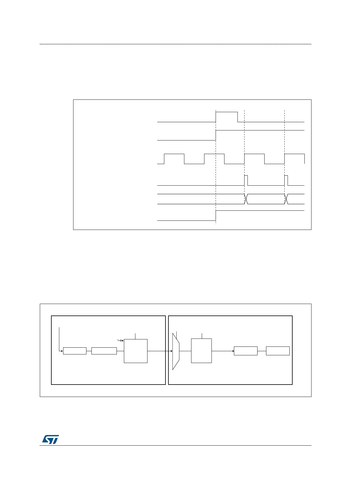
A rising edge on TI1 enables the counter and sets the TIF flag. The counter then counts on
ETR rising edges.
The delay between the rising edge of the ETR signal and the actual reset of the counter is
due to the resynchronization circuit on ETRP input.
Figure 314. Control circuit in external clock mode 2 + trigger mode
31.3.19 Timer synchronization
The TIMx timers are linked together internally for timer synchronization or chaining. When
one Timer is configured in Master Mode, it can reset, start, stop or clock the counter of
another Timer configured in Slave Mode.
Figure 315: Master/Slave timer example presents an overview of the trigger selection and
the master mode selection blocks.
Figure 315. Master/Slave timer example
069
7,)
&RXQWHUUHJLVWHU
&RXQWHUFORFN &.B&17 &.B36&
(75
&(1&17B(1
7,
D^ϯϯϭϭϴsϮ
ŽƵŶƚĞƌ
DĂƐƚĞƌ
ŵŽĚĞ
ĐŽŶƚƌŽů
hs
WƌĞƐĐĂůĞƌ
ůŽĐŬ
^ůĂǀĞ
ŵŽĚĞ
ĐŽŶƚƌŽů
ŽƵŶƚĞƌWƌĞƐĐĂůĞƌ
<ͺW^/dZϮdZ'Kϭ
DD^
^D^
d^
/ŶƉƵƚ
ƚƌŝŐŐĞƌ
ƐĞůĞĐƚŝŽŶ
d/Dϯ
d/DϮ
 Loading...


