Universal synchronous asynchronous receiver transmitter (USART) RM0351
1330/1830 DocID024597 Rev 5
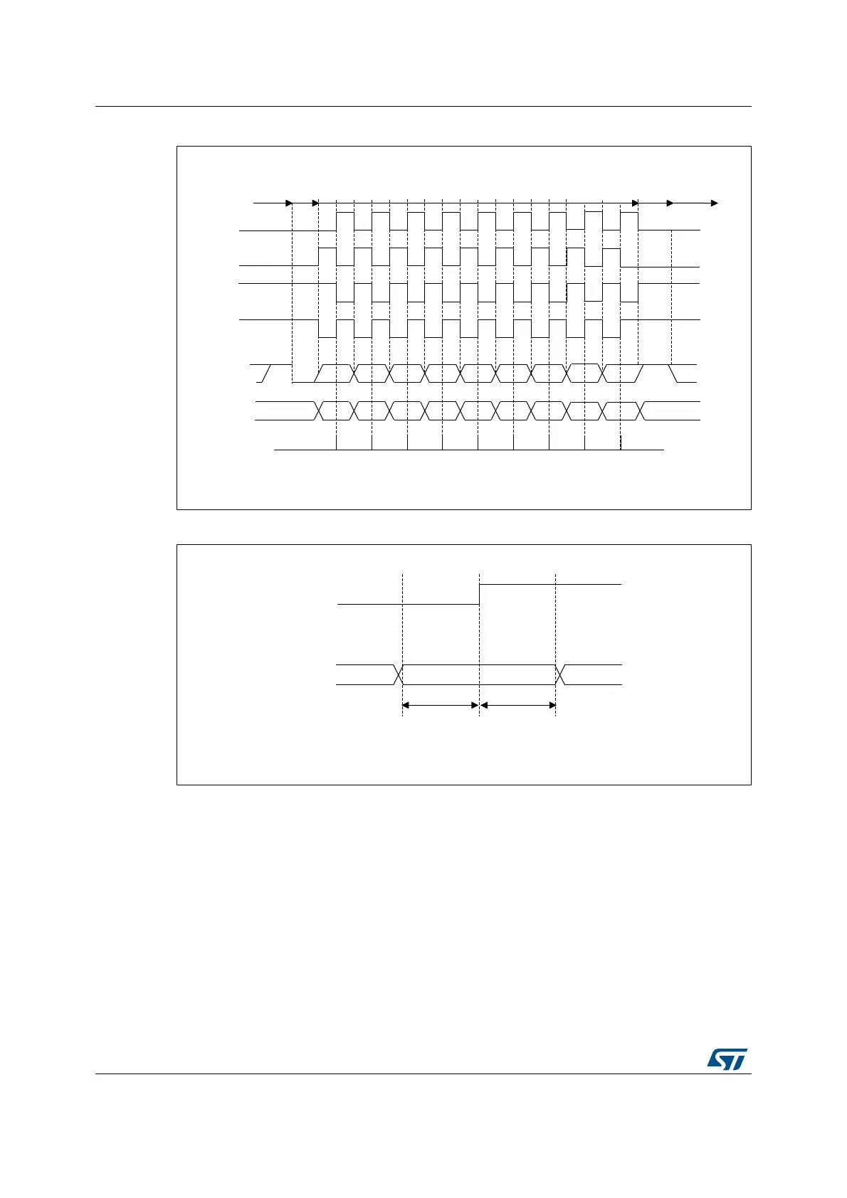
Figure 419. USART data clock timing diagram (M bits = 01)
Figure 420. RX data setup/hold time
Note: The function of CK is different in Smartcard mode. Refer to Section 40.5.13: USART
Smartcard mode for more details.
06Y9
06%
06%
/6%
/6%6WDUW
6WDUW 6WRS
,GOHRU
SUHFHGLQJ
WUDQVPLVVLRQ
,GOHRUQH[W
WUDQVPLVVLRQ
/%&/ELWFRQWUROVODVWGDWDSXOVH
&DSWXUH
VWUREH
'DWDRQ5;
IURPVODYH
'DWDRQ7;
IURPPDVWHU
&ORFN&32/
&3+$
&ORFN&32/
&3+$
&ORFN&32/
&3+$
&ORFN&32/
&3+$
6WRS
0ELWV GDWDELWV
06Y9
'DWDRQ5;IURPVODYH
&.
FDSWXUHVWUREHRQ&.ULVLQJ
HGJHLQWKLVH[DPSOH
9DOLG'$7$ELW
W
6(783
W
+2/'
W
6(783
W
+2/'
ELWWLPH
 Loading...


