DocID024597 Rev 5 921/1830
RM0351 Advanced-control timers (TIM1/TIM8)
981
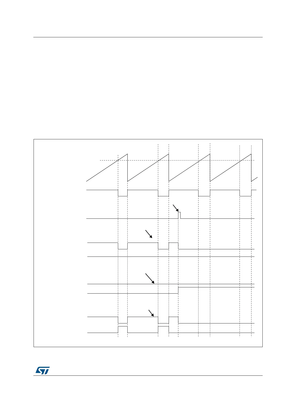
30.3.19 6-step PWM generation
When complementary outputs are used on a channel, preload bits are available on the
OCxM, CCxE and CCxNE bits. The preload bits are transferred to the shadow bits at the
COM commutation event. Thus you can program in advance the configuration for the next
step and change the configuration of all the channels at the same time. COM can be
generated by software by setting the COM bit in the TIMx_EGR register or by hardware (on
TRGI rising edge).
A flag is set when the COM event occurs (COMIF bit in the TIMx_SR register), which can
generate an interrupt (if the COMIE bit is set in the TIMx_DIER register) or a DMA request
(if the COMDE bit is set in the TIMx_DIER register).
The Figure 261 describes the behavior of the OCx and OCxN outputs when a COM event
occurs, in 3 different examples of programmed configurations.
Figure 261. 6-step generation, COM example (OSSR=1)
&&5[
2&[
2&[1
:ULWH&20WR
&RXQWHU&17
2&[5()
&20HYHQW
&&[(
&&[1(
2&[0
2&[
2&[1
&&[(
&&[1(
2&[
2&[1
&&[(
&&[1(
2&[0
([DPSOH
([DPSOH
([DPSOH
ZULWH2&[0WR
&&[(
&&[1(
2&[0 IRUFHGLQDFWLYH
&&[(
&&[1(
2&[0 IRUFHGLQDFWLYH
:ULWH&&[1(WR
DQG2&[0WR
ZULWH&&[1(WR
DQG2&[0WR
&&[(
&&[1(
2&[0 IRUFHGLQDFWLYH
DL
2&[0
 Loading...


