DocID024597 Rev 5 659/1830
RM0351 Digital camera interface (DCMI)
671
pixel , encoded in 8 bits, is stored as shown in Table 135.
The result is a monochrome image having the same resolution as the original YCbCr data.
20.5.6 Half resolution image extraction
This is a modification of the previous reception modes, being applicable to monochrome,
RGB or Y extraction modes.
This mode allows to only store a half resolution image. It is selected through OELS and LSM
control bits.
20.6 DCMI interrupts
Five interrupts are generated. All interrupts are maskable by software. The global interrupt
(IT_DCMI) is the OR of all the individual interrupts. Table 136 gives the list of all interrupts.
20.7 DCMI register description
All DCMI registers have to be accessed as 32-bit words, otherwise a bus error occurs.
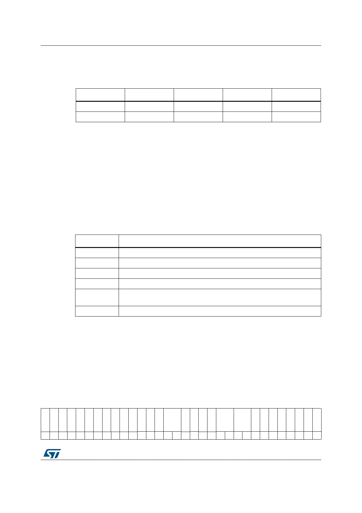
20.7.1 DCMI control register (DCMI_CR)
Address offset: 0x00
Reset value: 0x0000 0x0000
Table 135.Data storage in YCbCr progressive video format - Y extraction mode
Byte address 31:24 23:16 15:8 7:0
0 Y n + 3 Y n + 2 Y n + 1 Y n
4 Y n + 7 Y n + 6 Y n + 5 Y n + 4
Table 136.DCMI interrupts
Interrupt name Interrupt event
IT_LINE Indicates the end of line
IT_FRAME Indicates the end of frame capture
IT_OVR indicates the overrun of data reception
IT_VSYNC Indicates the synchronization frame
IT_ERR
Indicates the detection of an error in the embedded synchronization frame
detection
IT_DCMI Logic OR of the previous interrupts
313029282726252423222120191817161514131211109876543210
Res.
Res.
Res.
Res.
Res.
Res.
Res.
Res.
Res.
Res.
Res.
OELS
LSM
OEBS
BSM
Res.
ENABLE
Res.
Res.
EDM FCRC
VSPOL
HSPOL
PCKPOL
ESS
JPEG
CROP
CM
CAPTURE
rw rw rw rw rw rw rw rw rw rw rw rw rw rw rw rw rw rw
 Loading...


