DocID024597 Rev 5 999/1830
RM0351 General-purpose timers (TIM2/TIM3/TIM4/TIM5)
1052
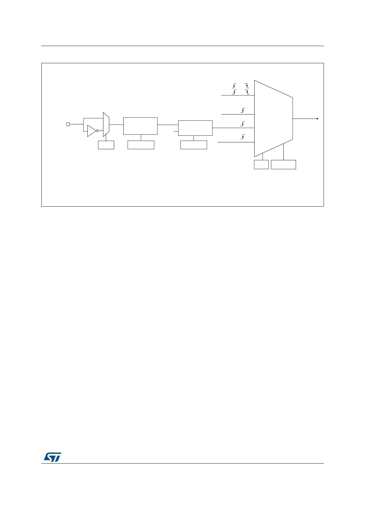
Figure 295. External trigger input block
For example, to configure the upcounter to count each 2 rising edges on ETR, use the
following procedure:
1. As no filter is needed in this example, write ETF[3:0]=0000 in the TIMx_SMCR register.
2. Set the prescaler by writing ETPS[1:0]=01 in the TIMx_SMCR register
3. Select rising edge detection on the ETR pin by writing ETP=0 in the TIMx_SMCR
register
4. Enable external clock mode 2 by writing ECE=1 in the TIMx_SMCR register.
5. Enable the counter by writing CEN=1 in the TIMx_CR1 register.
The counter counts once each 2 ETR rising edges.
The delay between the rising edge on ETR and the actual clock of the counter is due to the
resynchronization circuit on the ETRP signal.
([WHUQDOFORFN
PRGH
,QWHUQDOFORFN
PRGH
75*,
&.B,17
&.B36&
7,0[B60&5
606>@
069
LQWHUQDOFORFN
7,) RU
7,) RU
RU
(QFRGHU
PRGH
([WHUQDOFORFN
PRGH
(75)
(&(
7,0[B60&5
(73
(75SLQ
(75
'LYLGHU
)LOWHU
GRZQFRXQWHU
I
(753
7,0[B60&5
(736>@
7,0[B60&5
(7)>@
'76
 Loading...


