DocID024597 Rev 5 577/1830
RM0351 Analog-to-digital converters (ADC)
614
Refer to the electrical characteristics of the device datasheet for the sampling time value to
be applied when converting the V
BAT
/3 voltage.
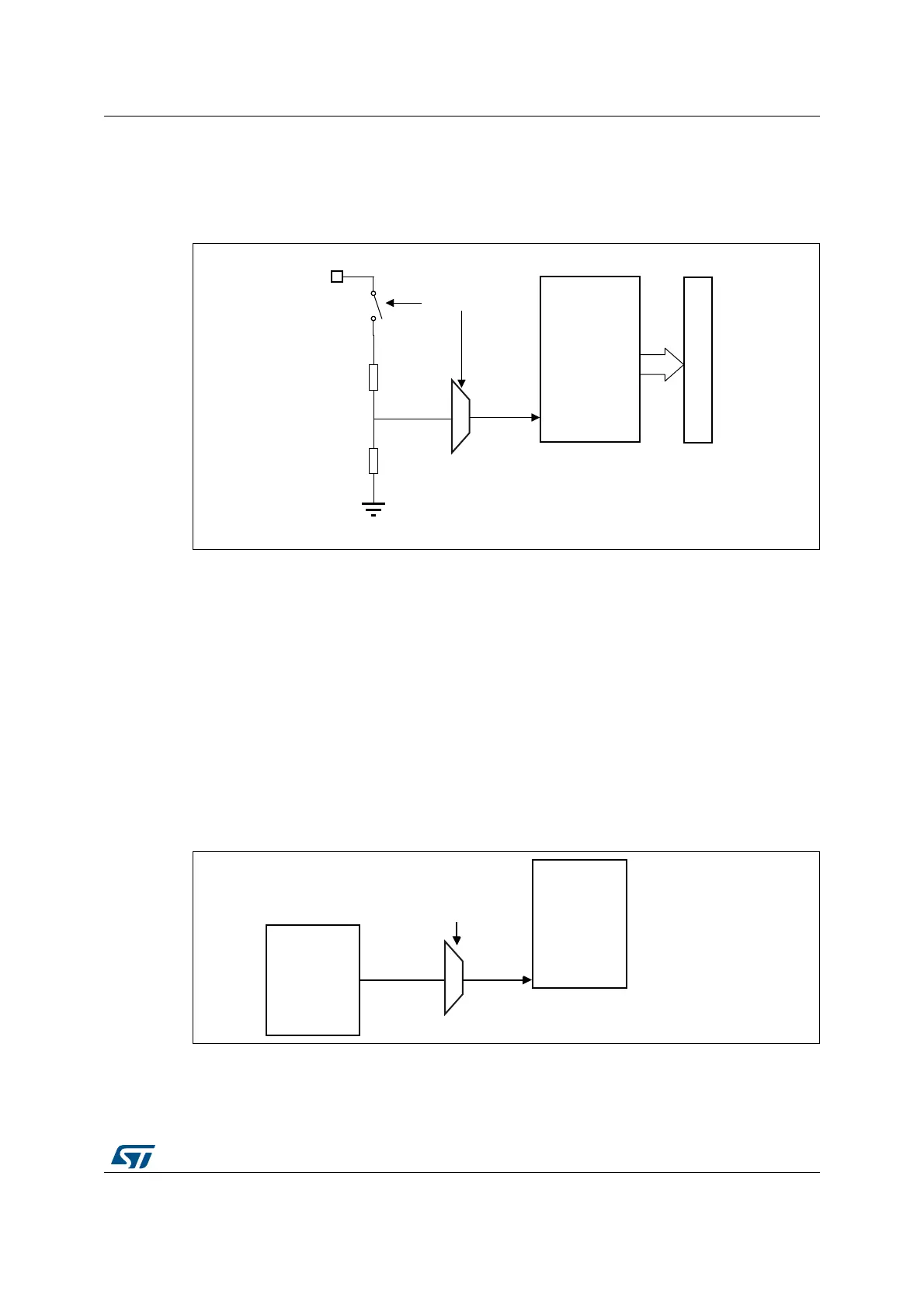
The figure below shows the block diagram of the V
BAT
sensing feature.
Figure 135. V
BAT
channel block diagram
1. The CH18_SEL bit must be set to enable the conversion of internal channels ADC1_IN18 and ADC3_IN18
(V
BAT
/3).
18.4.34 Monitoring the internal voltage reference
It is possible to monitor the internal voltage reference (V
REFINT
) to have a reference point for
evaluating the ADC V
REF+
voltage level.
The internal voltage reference is internally connected to the input channel 0 of the ADC1
(ADC1_IN0).
Refer to the electrical characteristics section of the STM32L4x5/STM32L4x6 datasheet for
the sampling time value to be applied when converting the internal voltage reference
voltage.
Figure 136 shows the block diagram of the V
REFINT
sensing feature.
Figure 136. V
REFINT
channel block diagram
1. The VREFEN bit into ADC_CCR register must be set to enable the conversion of internal channels
ADC1_IN0 (V
REFINT
).
06Y9
9
%$7
9
%$7
&+6(/FRQWUROELW
$'&[
$'&LQSXW
$GGUHVVGDWDEXV
069
9
5(),17
$'&
$'&B,1
$'&B95()(1
FRQWUROELW
,QWHUQDO
SRZHUEORFN
 Loading...


