DocID024597 Rev 5 515/1830
RM0351 Analog-to-digital converters (ADC)
614
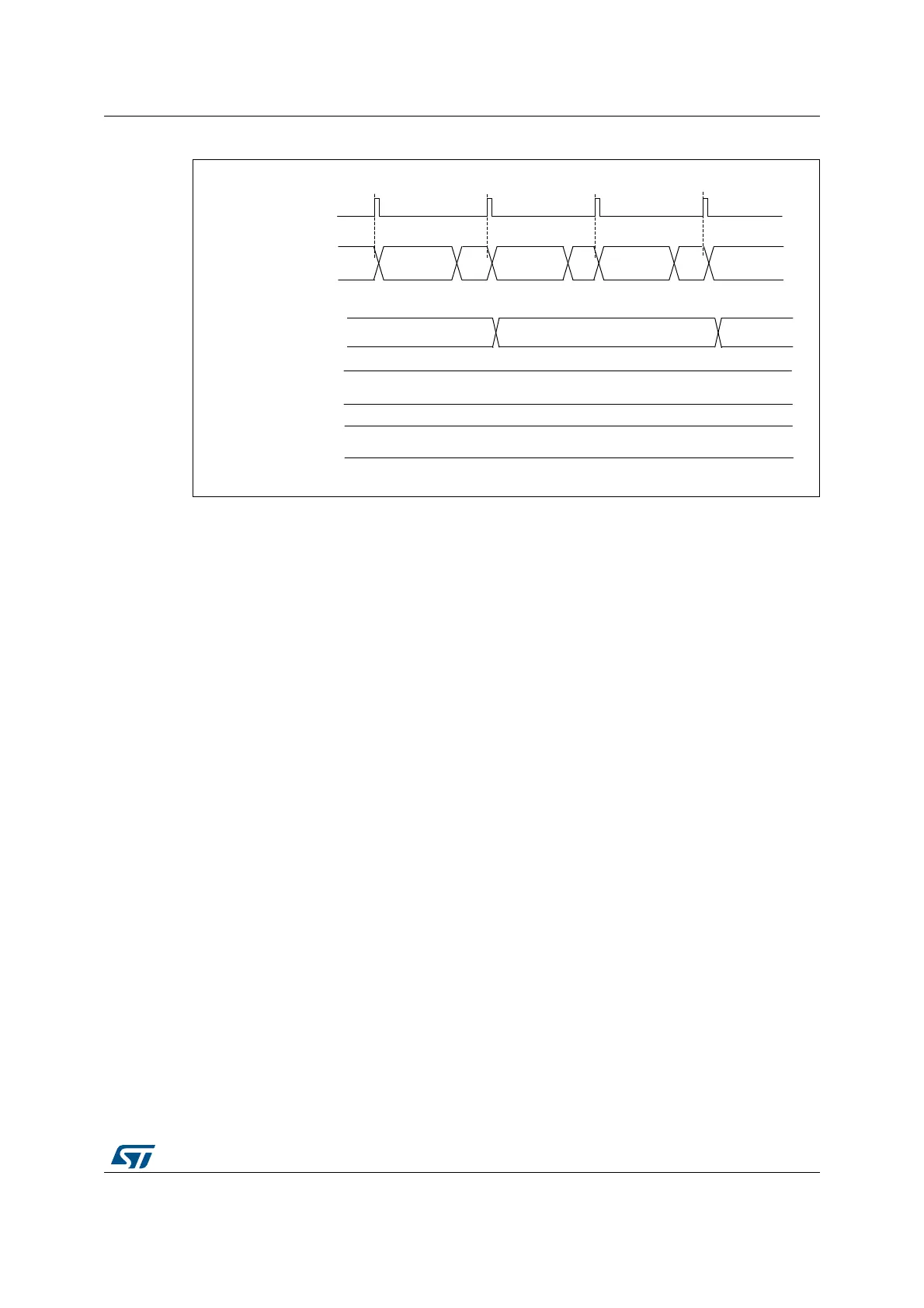
Figure 73. Mixing single-ended and differential channels
18.4.9 ADC on-off control (ADEN, ADDIS, ADRDY)
First of all, follow the procedure explained in Section 18.4.6: ADC Deep-power-down mode
(DEEPPWD) & ADC Voltage Regulator (ADVREGEN)).
Once DEEPPWD=0 and ADVREGEN=1, the ADC can be enabled and the ADC needs a
stabilization time of t
STAB
before it starts converting accurately, as shown in Figure 74. Two
control bits enable or disable the ADC:
• ADEN=1 enables the ADC. The flag ADRDY will be set once the ADC is ready for
operation.
• ADDIS=1 disables the ADC. ADEN and ADDIS are then automatically cleared by
hardware as soon as the analog ADC is effectively disabled.
Regular conversion can then start either by setting ADSTART=1 (refer to Section 18.4.18:
Conversion on external trigger and trigger polarity (EXTSEL, EXTEN, JEXTSEL, JEXTEN))
or when an external trigger event occurs, if triggers are enabled.
Injected conversions start by setting JADSTART=1 or when an external injected trigger
event occurs, if injected triggers are enabled.
Software procedure to enable the ADC
1. Clear the ADRDY bit in the ADC_ISR register by writing ‘1’.
2. Set ADEN=1.
3. Wait until ADRDY=1 (ADRDY is set after the ADC startup time). This can be done
using the associated interrupt (setting ADRDYIE=1).
4. Clear the ADRDY bit in the ADC_ISR register by writing ‘1’ (optional).
Caution: ADEN bit cannot be set during ADCAL=1 and 4 ADC clock cycle after the ADCAL bit is
cleared by hardware (end of the calibration).
$'&VWDWH
&$/)$&7B6>@ )
)
,QWHUQDO
FDOLEUDWLRQIDFWRU>@
&219&+
&$/)$&7B'>@
)
6LQJOHHQGHG
LQSXWVFKDQQHO
&219&+ &219&+
6LQJOHLQSXWV
FKDQQHO
) )
7ULJJHUHYHQW
5'<
5'< 5'<
06Y9
&219&+
5'<
'LIIHUHQWLDO
LQSXWVFKDQQHO
'LIIHUHQWLDO
LQSXWVFKDQQHO
 Loading...


