General-purpose timers (TIM2/TIM3/TIM4/TIM5) RM0351
996/1830 DocID024597 Rev 5
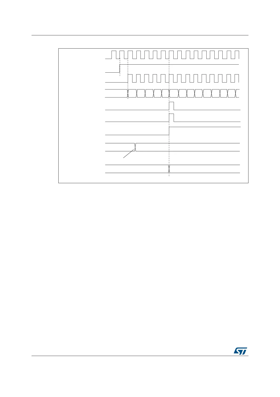
Figure 291. Counter timing diagram, Update event with ARPE=1 (counter overflow)
31.3.3 Clock selection
The counter clock can be provided by the following clock sources:
• Internal clock (CK_INT)
• External clock mode1: external input pin (TIx)
• External clock mode2: external trigger input (ETR)
• Internal trigger inputs (ITRx): using one timer as prescaler for another timer, for
example, you can configure Timer 13 to act as a prescaler for Timer 2. Refer to : Using
one timer as prescaler for another timer on page 1022 for more details.
Internal clock source (CK_INT)
If the slave mode controller is disabled (SMS=000 in the TIMx_SMCR register), then the
CEN, DIR (in the TIMx_CR1 register) and UG bits (in the TIMx_EGR register) are actual
control bits and can be changed only by software (except UG which remains cleared
automatically). As soon as the CEN bit is written to 1, the prescaler is clocked by the internal
clock CK_INT.
Figure 292 shows the behavior of the control circuit and the upcounter in normal mode,
without prescaler.
069
)'
&.B36&
7LPHUFORFN &.B&17
&RXQWHUUHJLVWHU
8SGDWHHYHQW8(9
&RXQWHURYHUIORZ
8SGDWHLQWHUUXSWIODJ
8,)
)
)
)
)$ )%
)&)
&(1
$XWRUHORDGSUHORDG
UHJLVWHU
:ULWHDQHZYDOXHLQ7,0[B$55
$XWRUHORDGDFWLYH
UHJLVWHU
)'
 Loading...


