Real-time clock (RTC) RM0351
1228/1830 DocID024597 Rev 5
38.6.19 RTC option register (RTC_OR)
Address offset: 0x4C
Backup domain reset value: 0x0000 0000
System reset: not affected
38.6.20 RTC backup registers (RTC_BKPxR)
Address offset: 0x50 to 0xCC
Backup domain reset value: 0x0000 0000
System reset: not affected
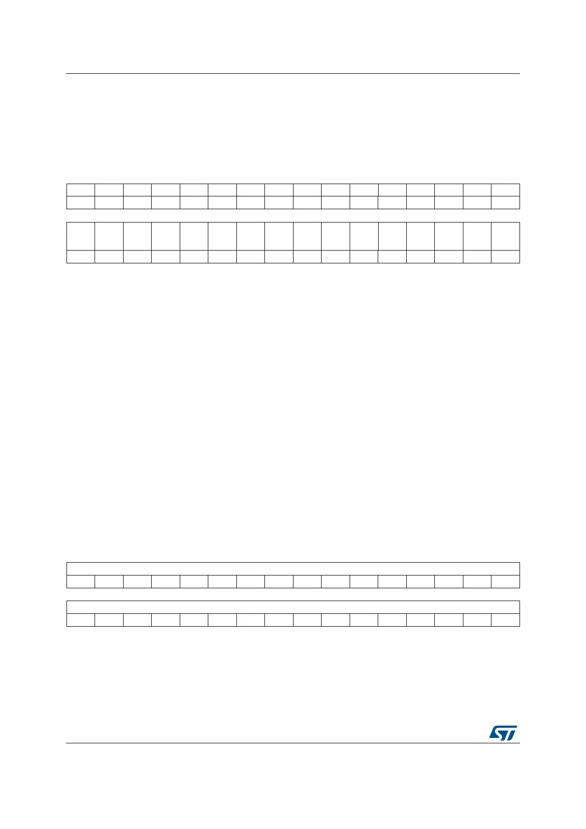
31 30 29 28 27 26 25 24 23 22 21 20 19 18 17 16
Res. Res. Res. Res. Res. Res. Res. Res. Res. Res. Res. Res. Res. Res. Res. Res.
1514131211109876543210
Res. Res. Res. Res. Res. Res. Res. Res. Res. Res. Res. Res. Res. Res.
RTC_
OUT_
RMP
RTC_
ALARM
_TYPE
rw rw
Bits 31:2 Reserved, must be kept at reset value.
Bit 1 RTC_OUT_RMP: RTC_OUT remap
Setting this bit allows to remap the RTC outputs on PB2 as follows:
RTC_OUT_RMP = ‘0’:
If OSEL/= ‘00’: RTC_ALARM is output on PC13
If OSEL= ‘00’ and COE = ‘1’: RTC_CALIB is output on PC13
RTC_OUT_RMP = ‘1’:
If OSEL /= ‘00’ and COE = ‘0’: RTC_ALARM is output on PB2
If OSEL = ‘00’ and COE = ‘1’: RTC_CALIB is output on PB2
If OSEL /= ‘00’ and COE = ‘1’: RTC_CALIB is output on PB2 and RTC_ALARM is output on
PC13.
Bit 0 RTC_ALARM_TYPE: RTC_ALARM output type on PC13
This bit is set and cleared by software
0: RTC_ALARM, when mapped on PC13, is open-drain output
1: RTC_ALARM, when mapped on PC13, is push-pull output
31 30 29 28 27 26 25 24 23 22 21 20 19 18 17 16
BKP[31:16]
rw rw rw rw rw rw rw rw rw rw rw rw rw rw rw rw
1514131211109876543210
BKP[15:0]
rw rw rw rw rw rw rw rw rw rw rw rw rw w rw rw
Bits 31:0 BKP[31:0]
The application can write or read data to and from these registers.
They are powered-on by V
BAT
when V
DD
is switched off, so that they are not reset by
System reset, and their contents remain valid when the device operates in low-power mode.
This register is reset on a tamper detection event, as long as TAMPxF=1.
 Loading...


