DocID024597 Rev 5 1349/1830
RM0351 Universal synchronous asynchronous receiver transmitter (USART)
1411
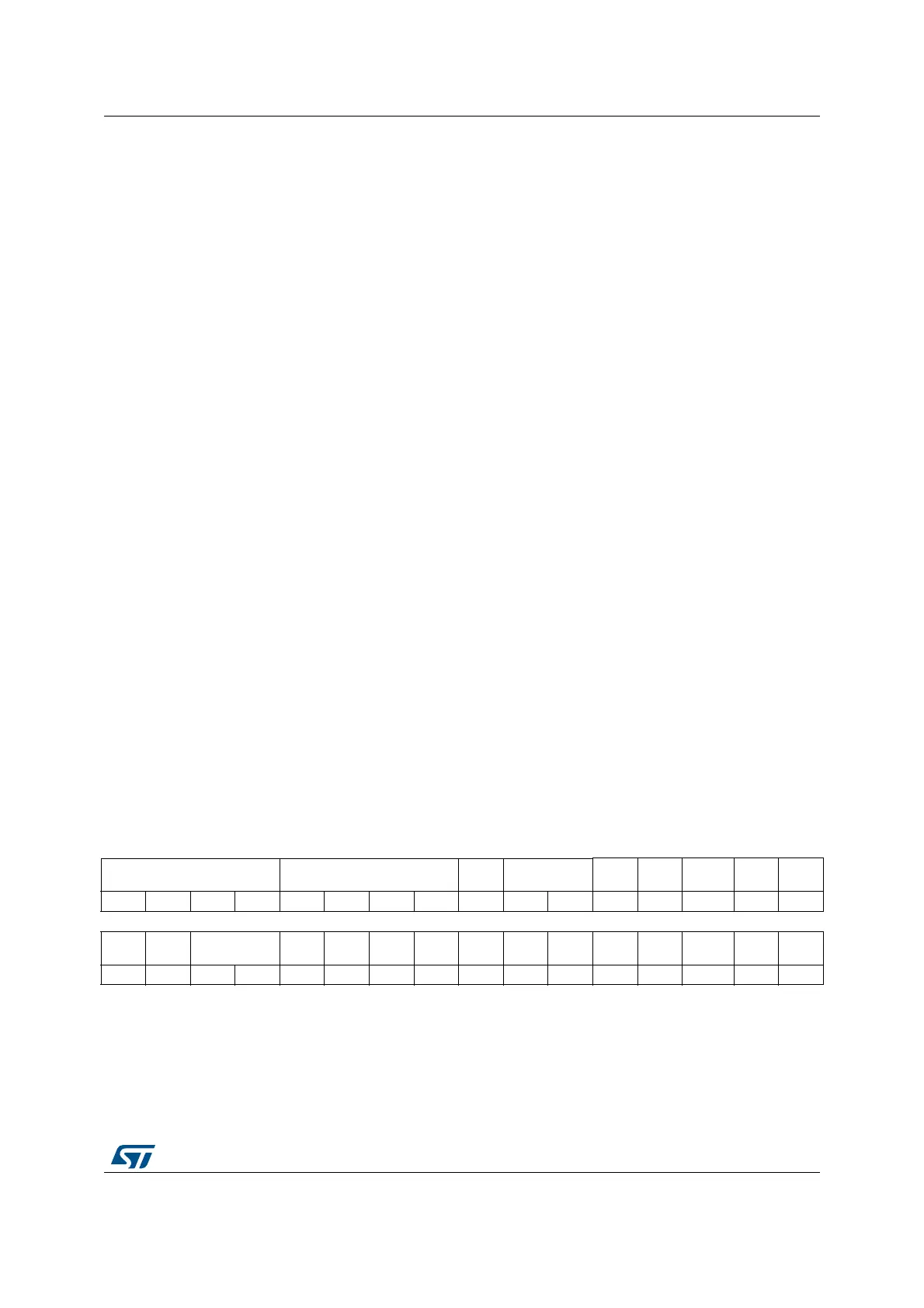
40.8.2 Control register 2 (USART_CR2)
Address offset: 0x04
Reset value: 0x0000
Bit 2 RE: Receiver enable
This bit enables the receiver. It is set and cleared by software.
0: Receiver is disabled
1: Receiver is enabled and begins searching for a start bit
Bit 1 UESM: USART enable in Stop mode
When this bit is cleared, the USART is not able to wake up the MCU from Stop mode.
When this bit is set, the USART is able to wake up the MCU from Stop mode, provided that
the USART clock selection is HSI16 or LSE in the RCC.
This bit is set and cleared by software.
0: USART not able to wake up the MCU from Stop mode.
1: USART able to wake up the MCU from Stop mode. When this function is active, the clock
source for the USART must be HSI16 or LSE (see
Section Reset and clock control
(RCC)
.
Note: It is recommended to set the UESM bit just before entering Stop mode and clear it on
exit from Stop mode.
If the USART does not support the wakeup from Stop feature, this bit is reserved and
forced by hardware to ‘0’. Please refer to Section 40.4: USART implementation on
page 1304.
Bit 0 UE: USART enable
When this bit is cleared, the USART prescalers and outputs are stopped immediately, and
current operations are discarded. The configuration of the USART is kept, but all the status
flags, in the USART_ISR are set to their default values. This bit is set and cleared by
software.
0: USART prescaler and outputs disabled, low-power mode
1: USART enabled
Note: In order to go into low-power mode without generating errors on the line, the TE bit
must be reset before and the software must wait for the TC bit in the USART_ISR to be
set before resetting the UE bit.
The DMA requests are also reset when UE = 0 so the DMA channel must be disabled
before resetting the UE bit.
31 30 29 28 27 26 25 24 23 22 21 20 19 18 17 16
ADD[7:4] ADD[3:0] RTOEN ABRMOD[1:0] ABREN
MSBFI
RST
DATAINV TXINV RXINV
rw rw rw rw rw rw rw rw rw rw rw rw rw rw rw rw
1514131211109876543 2 10
SWAP LINEN STOP[1:0] CLKEN CPOL CPHA LBCL Res. LBDIE LBDL ADDM7 Res. Res. Res. Res.
rw rw rw rw rw rw rw rw rw rw rw
 Loading...


