DocID024597 Rev 5 667/1830
RM0351 Digital camera interface (DCMI)
671
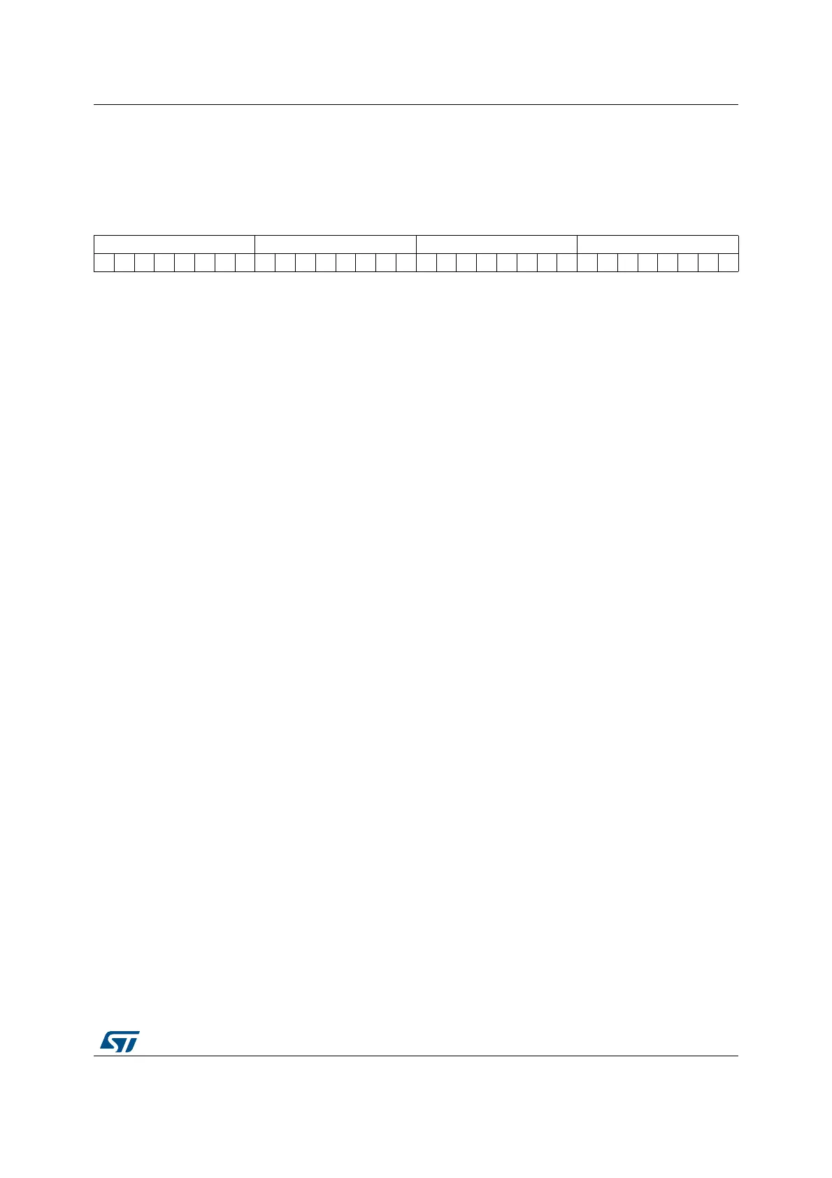
20.7.7 DCMI embedded synchronization code register (DCMI_ESCR)
Address offset: 0x18
Reset value: 0x0000 0x0000
313029282726252423222120191817161514131211109876543210
FEC LEC LSC FSC
rw rw rw rw rw rw rw rw rw rw rw rw rw rw rw rw rw rw rw rw rw rw rw rw rw rw rw rw rw rw rw rw
Bits 31:24 FEC: Frame end delimiter code
This byte specifies the code of the frame end delimiter. The code consists of 4
bytes in the form of 0xFF, 0x00, 0x00, FEC.
If FEC is programmed to 0xFF, all the unused codes (0xFF0000XY) are
interpreted as frame end delimiters.
Bits 23:16 LEC: Line end delimiter code
This byte specifies the code of the line end delimiter. The code consists of 4
bytes in the form of 0xFF, 0x00, 0x00, LEC.
Bits 15:8 LSC: Line start delimiter code
This byte specifies the code of the line start delimiter. The code consists of 4
bytes in the form of 0xFF, 0x00, 0x00, LSC.
Bits 7:0 FSC: Frame start delimiter code
This byte specifies the code of the frame start delimiter. The code consists of 4
bytes in the form of 0xFF, 0x00, 0x00, FSC.
If FSC is programmed to 0xFF, no frame start delimiter is detected. But, the 1
st
occurrence of LSC after an FEC code will be interpreted as a start of frame
delimiter.

 Loading...