DocID024597 Rev 5 783/1830
RM0351 Liquid crystal display controller (LCD)
787
Note: The data in this register can be updated any time, however the new values are applied only
at the beginning of the next frame (except for UDDIE, SOFIE that affect the device behavior
immediately).
The new value of CC[2:0] bits is also applied immediately but its effect on device is delayed
at the beginning of next frame by the voltage generator.
Reading this register obtains the last value written in the register and not the configuration
used to display the current frame.
Note: When BUFEN bit is set in the LCD_CR register, low resistor divider network is automatically
disabled whatever the HD or PON[2:0] bits configuration.
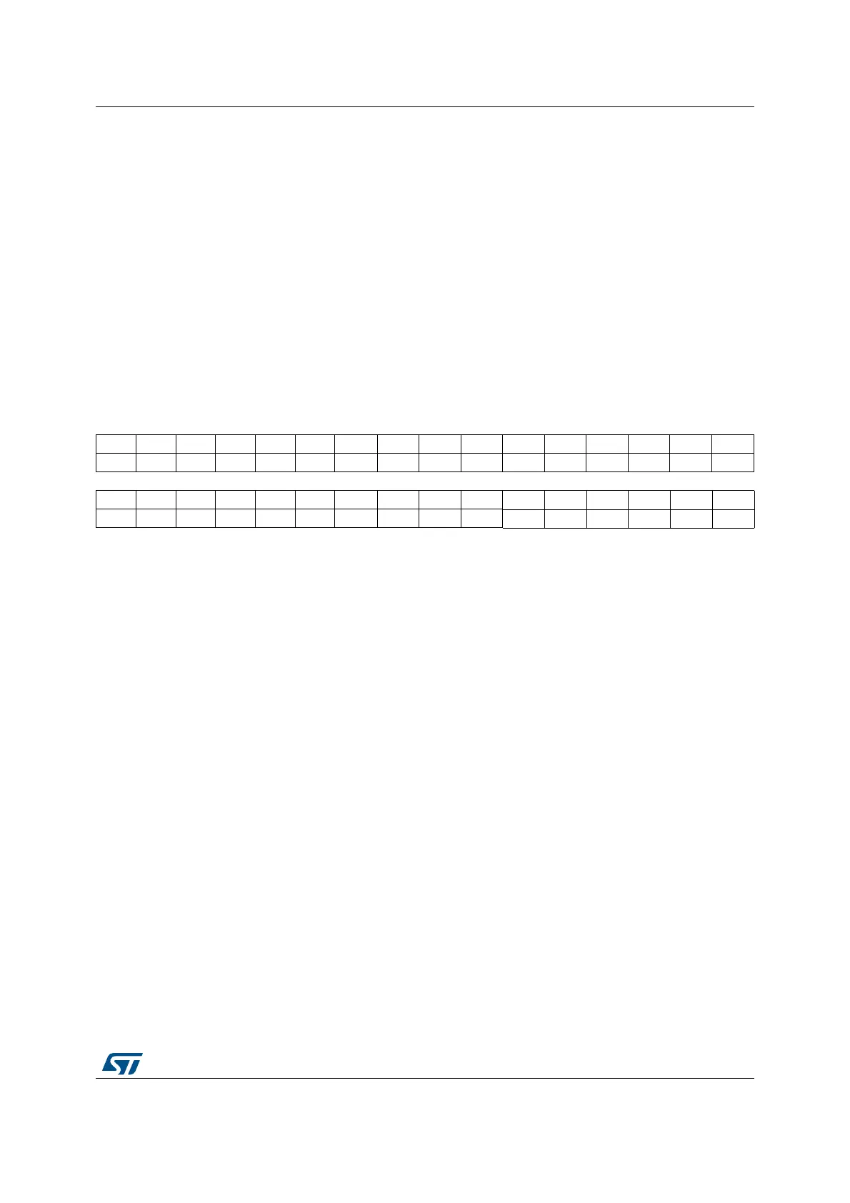
25.6.3 LCD status register (LCD_SR)
Address offset: 0x08
Reset value: 0x0000 0020
31 30 29 28 27 26 25 24 23 22 21 20 19 18 17 16
Res. Res. Res. Res. Res. Res. Res. Res. Res. Res. Res. Res. Res. Res. Res. Res.
15 14 13 12 11 10 9 8 7 6 5 4 3 2 1 0
Res. Res. Res. Res. Res. Res. Res. Res. Res. Res. FCRSF RDY UDD UDR SOF ENS
rrrrsrr
Bits 31:6 Reserved, must be kept at reset value
Bit 5 FCRSF: LCD Frame Control Register Synchronization flag
This bit is set by hardware each time the LCD_FCR register is updated in the LCDCLK
domain. It is cleared by hardware when writing to the LCD_FCR register.
0: LCD Frame Control Register not yet synchronized
1: LCD Frame Control Register synchronized
Bit 4 RDY: Ready flag
This bit is set and cleared by hardware. It indicates the status of the step-up converter.
0: Not ready
1: Step-up converter is enabled and ready to provide the correct voltage.
Bit 3 UDD: Update Display Done
This bit is set by hardware. It is cleared by writing 1 to the UDDC bit in the LCD_CLR register.
The bit set has priority over the clear.
0: No event
1: Update Display Request done. A UDD interrupt is generated if the UDDIE bit in the
LCD_FCR register is set.
Note: If the device is in Stop mode (PCLK not provided) UDD will not generate an interrupt
even if UDDIE = 1.
If the display is not enabled the UDD interrupt will never occur.

 Loading...