Advanced-control timers (TIM1/TIM8) RM0351
972/1830 DocID024597 Rev 5
Note: Refer to Figure 255: Break and Break2 circuitry overview.
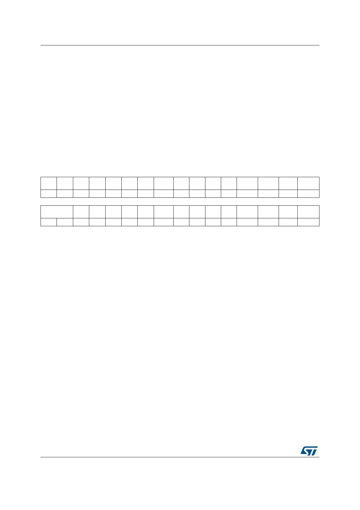
30.4.28 TIM8 option register 2 (TIM8_OR2)
Address offset: 0x60
Reset value: 0x0000 0001
Bit 0 BK2INE: BRK2 BKIN input enable
This bit enables the BKIN2 alternate function input for the timer’s BRK2 input. BKIN2 input is
‘ORed’ with the other BRK2 sources.
0: BKIN2 input disabled
1: BKIN2 input enabled
Note: This bit can not be modified as long as LOCK level 1 has been programmed (LOCK bits
in TIMx_BDTR register).
31 30 29 28 27 26 25 24 23 22 21 20 19 18 17 16
Res. Res. Res. Res. Res. Res. Res. Res. Res. Res. Res. Res. Res. Res. Res.
ETRSEL
[2]
rw
15 14 13 12 11 10 9 8 7 6 5 4 3 2 1 0
ETRSEL[1:0] Res. Res.
BKCM
P2P
BKCM
P1P
BKINP
BKDF1
BK2E
Res. Res. Res. Res. Res.
BKCMP2
E
BKCMP
1E
BKINE
rw rw rw rw rw rw rw rw rw
Bits 31:17 Reserved, must be kept at reset value
Bits 16:14 ETRSEL[2:0]: ETR source selection
These bits select the ETR input source.
000: TIM8_ETR is selected with the ETR_ADC3_RMP and ETR_ADC2_RMP bitfield in
TIM8_OR1 register
001: COMP1 output connected to ETR input
010: COMP2 output connected to ETR input
others: Reserved
Note: These bits can not be modified as long as LOCK level 1 has been programmed (LOCK
bits in TIMx_BDTR register).
Bits 13:12 Reserved, must be kept at reset value
Bit 11 BKCMP2P: BRK COMP2 input polarity
This bit selects the COMP2 input sensitivity. It must be programmed together with the BKP
polarity bit.
0: COMP2 input is active high
1: COMP2 input is active low
Note: This bit can not be modified as long as LOCK level 1 has been programmed (LOCK bits
in TIMx_BDTR register).
Bit 10 BKCMP1P: BRK COMP1 input polarity
This bit selects the COMP1 input sensitivity. It must be programmed together with the BKP
polarity bit.
0: COMP1 input is active high
1: COMP1 input is active low
Note: This bit can not be modified as long as LOCK level 1 has been programmed (LOCK bits
in TIMx_BDTR register).

 Loading...