Step 3
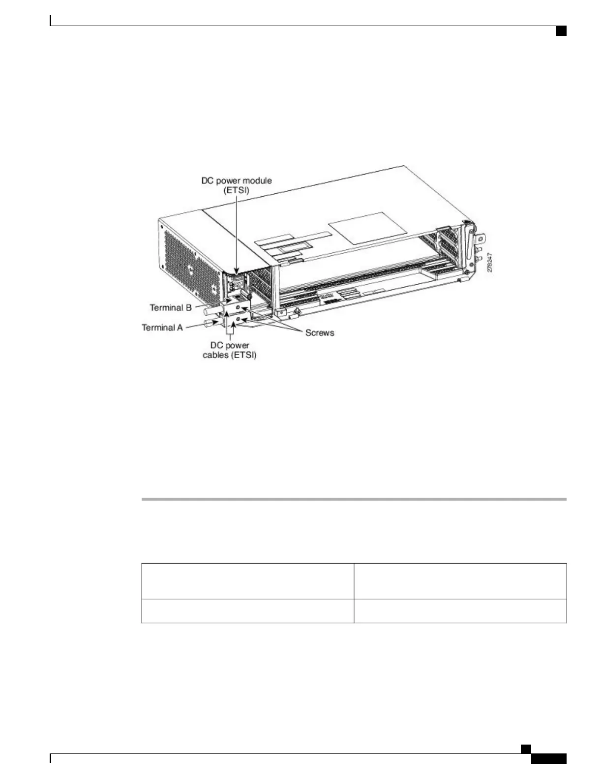
Attach the DC ETSI power cables to the DSUB power connectors of the DC power module (see the figure
below).
Step 4
Tighten the screws to a torque value of 4 in-lb (0.45 N-m) to secure the cable.
Figure 50: Connecting Office Power
—
DC Power Module (ETSI Only)
Use only pressure terminal connectors, such as ring and fork types, when terminating the battery,
battery return, and frame ground conductors.
Note
Before you make any crimp connections, coat all bare conductors (battery, battery return, and
frame ground) with an appropriate antioxidant compound. Bring all unplated connectors, braided
strap, and bus bars to a bright finish, then coat with an antioxidant before you connect them. You
do not need to prepare tinned, solder-plated, or silver-plated connectors and other plated connection
surfaces, but always keep them clean and free of contaminants.
Caution
When terminating power, return, and frame ground, do not use soldering lug, screwless (push-in)
connectors, quick-connect, or other friction-fit connectors.
Caution
Step 5
Return to your originating procedure (NTP).
DLP-L52 Turning On and Verifying AC Office Power on the NCS 2002 Shelf
This task measures the power to verify correct power
and returns for the NCS 2002 shelf.
Purpose
VoltmeterTools/Equipment
Cisco NCS 2000 Series Hardware Installation Guide
91
Connecting Power and Ground
DLP-L52 Turning On and Verifying AC Office Power on the NCS 2002 Shelf