Step 2
Tighten the screws of the SCSI connector to a torque value of 4 in-lb (0.45 N-m) using #2 Philips Dynamometric
screwdriver.
Step 3
Bend the cable at an angle of 90° to exit from the left side or the right side (see the figures below ).
Step 4
Return to your originating procedure (NTP).
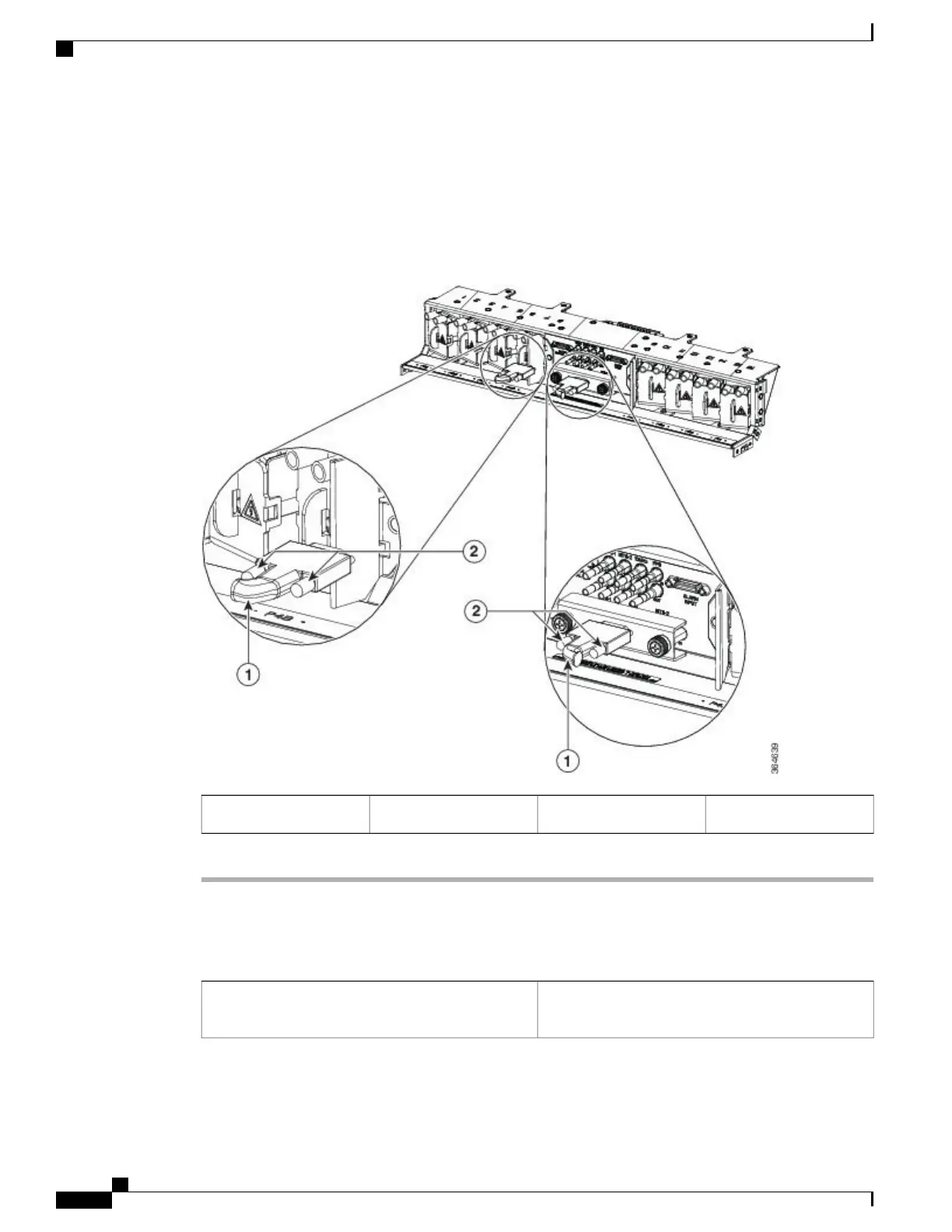
Figure 201: Installing the Alarm Cable
—
Left and Right Exit
Screws2Alarm cable1
DLP-L77 Installing Timing Wires on NCS 2015
This task installs the timing cables on the power input
panel.
Purpose
Cisco NCS 2000 Series Hardware Installation Guide
352
Connecting and Routing the Cables
DLP-L77 Installing Timing Wires on NCS 2015