•
One USB port to support passive unit remote inventory connection
•
Two BITS connections (IN and OUT) for network synchronization that is supported by mini BNC
Each ANSI DC power module has:
•
Two terminal block connectors with -48V, RET for power terminals A and B
•
One RJ-45 port for EMS connection
•
One USB port to support passive unit remote inventory connection
•
Two BITS connections (IN and OUT) for network synchronization supported by four wire-wrap pins
The DC power module has a single dual-color (red and green) LED on the faceplate. When the battery is not
connected, the LED is OFF. Green LED indicates that the battery is connected and the power module functions
properly. Red LED indicates that the battery is connected but an alarm is present due to secondary fuse break
(48 V). The DC power module does not support the lamp test procedure.
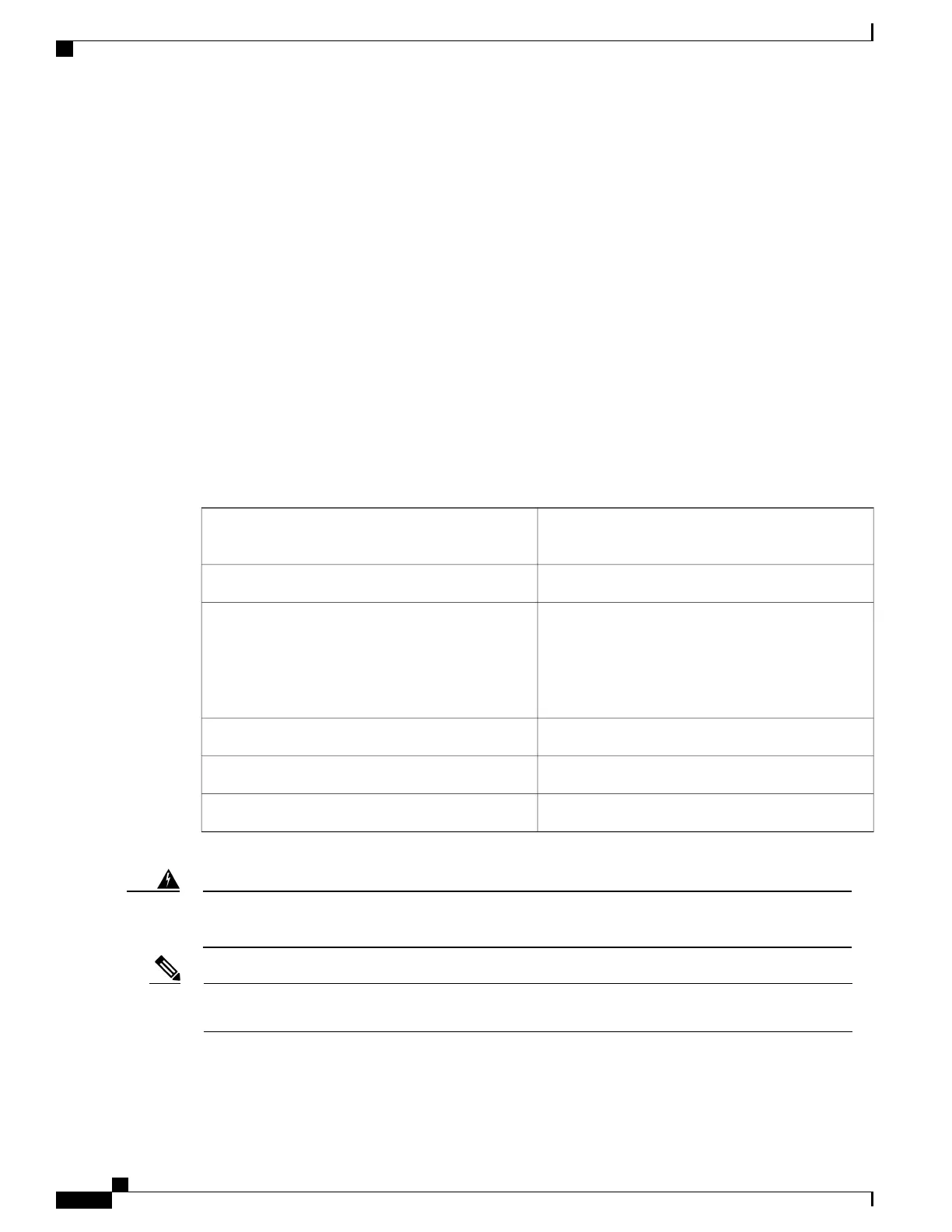
NTP-L33 Installing the Power Module in the NCS 2002 Shelf
This procedure installs the power module in the NCS
2002 system.
Purpose
#2 Phillips screwdriverTools/Equipment
•
Connect the chassis to the office ground. For
detailed instructions on how to ground the
chassis, refer to the Electrostatic Discharge and
Grounding Guide for Cisco NCS 2000 Series .
Prerequisite Procedures
RequiredRequired/As Needed
OnsiteOnsite/Remote
NoneSecurity Level
The plug-socket combination must be accessible at all times because it serves as the main
disconnecting device. Statement 1019
Warning
During the system startup or fan-tray replacement, the inventory data of the fan-tray assembly and the
power module is displayed in the Inventory tab of CTC after a delay of approximately 6 minutes.
Note
Cisco NCS 2000 Series Hardware Installation Guide
126
Installing the Cisco NCS 2002 Door and Other Modules
NTP-L33 Installing the Power Module in the NCS 2002 Shelf