OnsiteOnsite/Remote
NoneSecurity Level
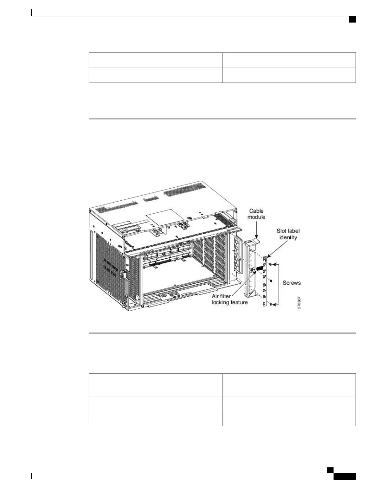
Procedure
Step 1
Insert the air filter locking feature on the cable module. (See the figure below)
Step 2
Attach the slot label identity on the cable module, with screws.
Step 3
Mount the cable module on the chassis, and tighten the screws to a torque value of 4 in-lb (0.45 N-m) to attach
the cable module to the NCS 2006 shelf.
Figure 129: Installing the Cable Module
Step 4
Return to your originating procedure (NTP).
DLP-L25 Routing and Locking Cables
This task routes and locks the cables on the NCS 2006
system.
Purpose
NoneTools/Equipment
NonePrerequisite Procedures
Cisco NCS 2000 Series Hardware Installation Guide
225
Connecting and Routing the Cables
DLP-L25 Routing and Locking Cables