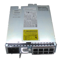
The NCS 2002 shelf has a BITS-IN and BITS-OUT port on the power module. The BITS-IN and BITS-OUT
connections are supported by:
•
Wire-wrap pins and mini-BNC connectors on the AC power module.
◦
◦
Mini-BNC connectors on the ETSI DC power module.
◦
Wire-wrap pins on the ANSI DC power module.
For timing connection, use 100-ohm shielded BITS clock cable pair #22 or #24 AWG (0.51 mm² [0.020
inch] or 0.64 mm² [0.0252 inch]) twisted-pair T1-type.
Note
Refer to Telcordia SR-NWT-002224 for rules about provisioning timing references.Note
AC Power Module
The AC power module converts the AC input current to DC output current.
Each AC power module has:
•
One AC single phase three poles (line L, Neutral N, and Protective Earth PE) input connector
•
One RJ-45 port for EMS connection
•
One USB port to support passive unit remote inventory connection
•
Two BITs connections (IN and OUT) for network synchronization supported by mini BNC
•
Two BITs connections (IN and OUT) for network synchronization supported by four wire-wrap pins
The AC power module has a single dual-color (red and green) LED on the faceplate. When the AC power
line is not connected, the LED is OFF. Green LED indicates that the AC power line is connected and the
power module is functioning properly. Red LED indicates that the AC power line is connected but an alarm
is present due to secondary (48 V) fuse break. The shelf controller card controls the conditions that result in
triggering the LED. The LED can be overwritten by the shelf controller card (TNC, TNCE, TSC, or TSCE)
in all the three states (OFF/red/green). The AC power module supports the lamp test procedure and the LED
changes its color or state. The fans in the NCS 2002 shelf cool the AC module and guarantee proper operation
across the complete operating temperature or output power range.
DC Power Module
The NCS 2002 system can be powered by redundant DC power lines, however a single power line can power
the entire NCS 2002 system. The DC power module draws the power from the batteries to turn on the NCS
2002.
Each ETSI DC power module has:
•
Two input battery connectors (two poles): -48V, RET for power terminals A and B.
•
One RJ-45 port for EMS connection
Cisco NCS 2000 Series Hardware Installation Guide
125
Installing the Cisco NCS 2002 Door and Other Modules
AC Power Module
 Loading...


