Step 3
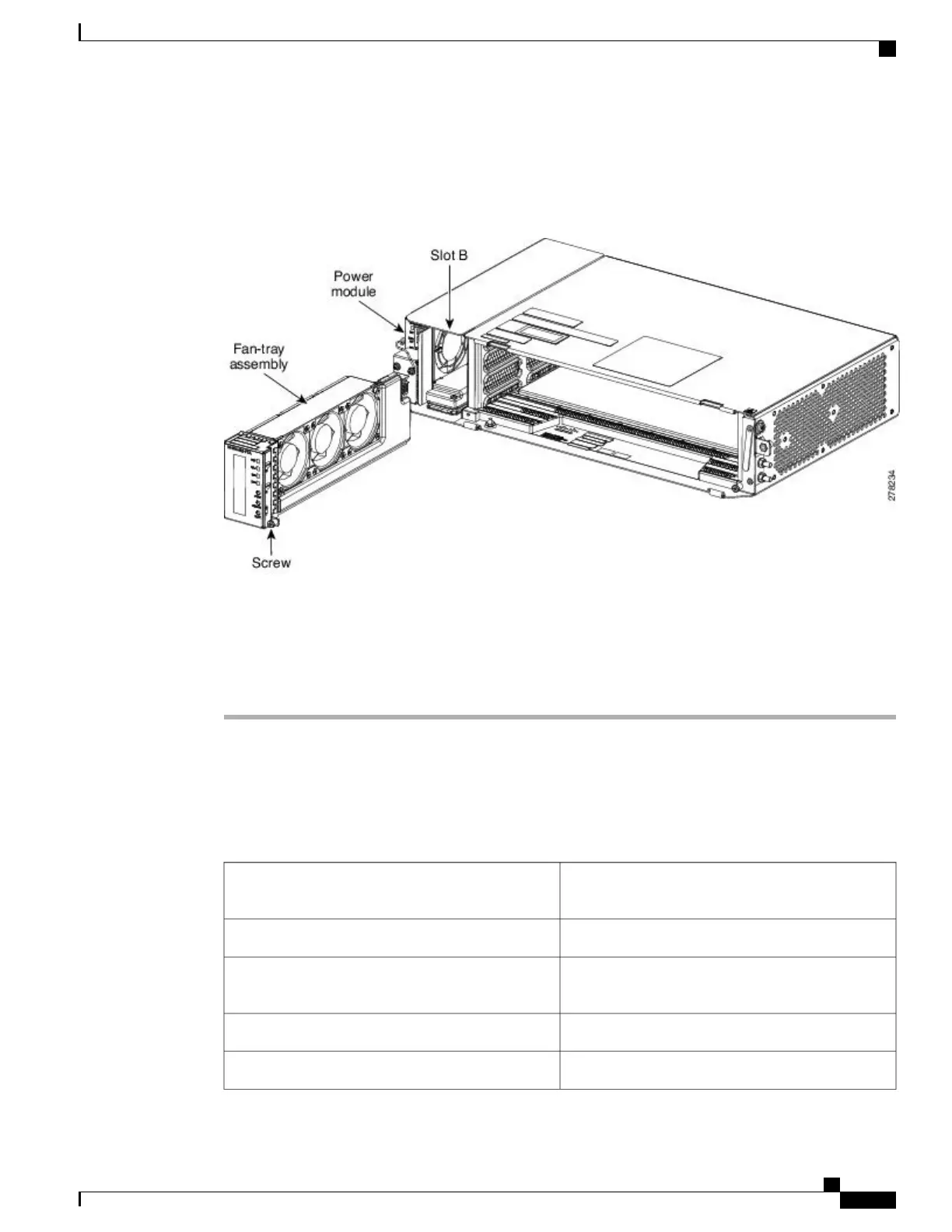
When the fans have stopped, pull the fan-tray assembly completely out of the shelf assembly (see the figure
below).
Figure 251: Fan-Tray Extracted
Step 4
Slide the new fan-tray assembly into the shelf assembly until the electrical plug at the rear of the tray plugs
into the corresponding receptacle on the backplane.
Step 5
To verify that the tray has plugged into the backplane, ensure that the LCD on the front of the fan-tray is
activated.
Stop. You have completed this procedure.
NTP-L26 Replacing the Fan-Tray Assembly of the NCS 2006 Shelf
Assembly
This procedure replaces the fan-tray assembly of the
NCS 2006 shelf assembly.
Purpose
Small slot-head screwdriverTools/Equipment
NTP-L11 Installing the Fan-Tray Assembly in the
NCS 2006 Shelf, on page 296
Prerequisite Procedures
RequiredRequired/As Needed
OnsiteOnsite/Remote
Cisco NCS 2000 Series Hardware Installation Guide
457
Maintaining the NCS 2002, NCS 2006, and NCS 2015 Shelves
NTP-L26 Replacing the Fan-Tray Assembly of the NCS 2006 Shelf Assembly