Power tray2DC power module1
Step 2
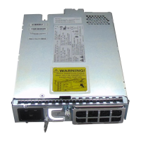
Using two hands to support the power module, slide it into the power slot (see the figure above).
Step 3
Secure the power module into the power tray using the snap hook.
Step 4
Repeat the above steps for the other DC power modules.
Step 5
Return to your originating procedure (NTP).
LCD Unit
The LCD unit is integrated with the fan tray assembly and consists of an LCD display panel, push button, and
shelf-level LED indicators on the NCS 2015 system.
The shelf controller card (TNCS) powers the 16 x 2 character LCD screen. The LCD screen displays the shelf
name, shelf IP address, and software version currently used. The LCD screen also provides slot-level and
port-level information of all card slots, including the number of critical, major, and minor alarms. The display
contrast is automatically adjusted for a clearer view. The three accessible push buttons (SLOT, STATUS, and
PORT) on the LCD unit are used to set parameters at the slot-level and port-level. There are three alarm LEDs
(CRIT, MAJ, and MIN) on the LCD unit that indicate whether a critical, major, or minor alarm is present
anywhere on the NCS 2015 shelf. There is also a Fan Fail LED. When the fan-tray assembly is not functioning
or when the power line is not connected, the LED is OFF. When the power line is connected and if there is
no TNCS card installed in the NCS2015 shelf, then the LED is OFF. A red LED indicates an alarm in the
fan-tray assembly. A green LED indicates that the fan-tray assembly is functioning, the power line is connected,
and the power module is functioning properly. The shelf controller card controls the conditions that result in
triggering the LEDs. The LEDs can be overwritten by the shelf controller card (TNCS) in all the three states
(OFF/red/green). The LCD unit supports the lamp test procedure and the LEDs changes its color or state.
Fan-Tray Assembly
The fan-tray supported on the NCS 2015 shelf is NCS2015-FTA.
The fan-tray assembly is located on the front side of the NCS 2015 shelf. The fan-tray is removable and holds
the fan-control circuitry and the fans for the NCS 2015 shelf. The fan tray has 9 x 92mm x 48mm fans that
are capable of pulling enough air to cool up to 300 W per LC with optimum placement and components at
both 27C NEBS acoustic level and 55C NEBS extended temperature range. The fan tray also accommodates
LCD panel and its circuitry. The fan-tray assembly supports the lamp test procedure. After you install the fan
tray, you should only access it when a fan failure occurs.
Fan Speed
The fan speed is controlled by the TNCS card temperature sensors. The sensors measure the input air
temperature at the fan-tray assembly. If the TNCS card fails, the fans automatically shift to high speed. The
temperature that the TNCS sensors measure appears on the LCD screen.
Cisco NCS 2000 Series Hardware Installation Guide
392
Installing the Cisco NCS 2015 Door and Other Modules
LCD Unit
 Loading...
