As neededRequired/As Needed
OnsiteOnsite/Remote
NoneSecurity Level
Procedure
Step 1
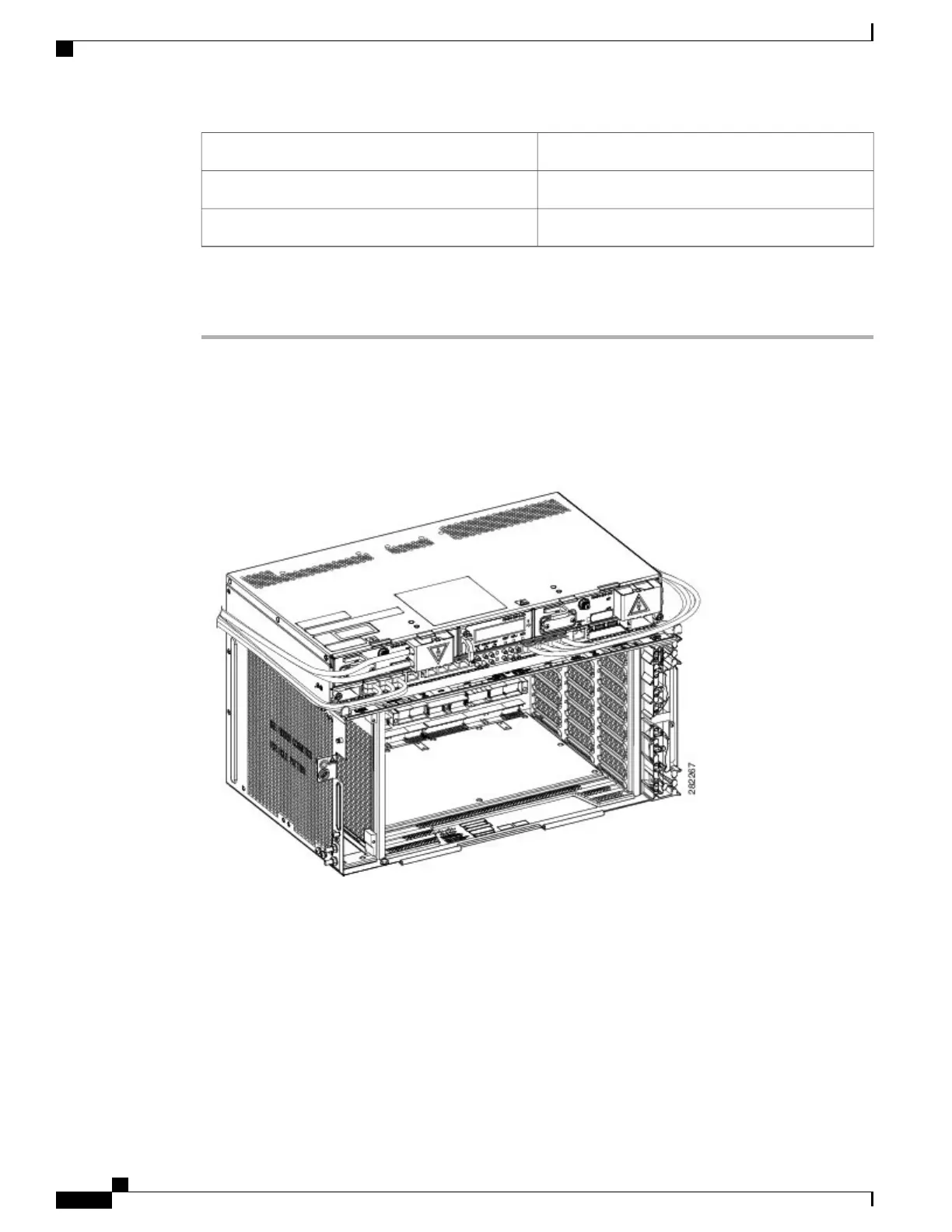
Route the ECU cables on both the ECU ejectors.
The following figure shows an example of ECU cable routing. This allows you to close the front door. Ensure
an extra length of ECU cable is available to allow cable management during extraction of the power module.
Figure 130: ECU module Cable Routing
It is also possible to manage the extraction of the power module without adding the extra length of ECU cable
by reducing the number of cables in the right exit area (see Diagram 1 of the figure below ). An extra length
Cisco NCS 2000 Series Hardware Installation Guide
226
Connecting and Routing the Cables
DLP-L25 Routing and Locking Cables