of ECU cable is required in the left exit area to manage the USB connections (see Diagram 2 of the figure
below ).
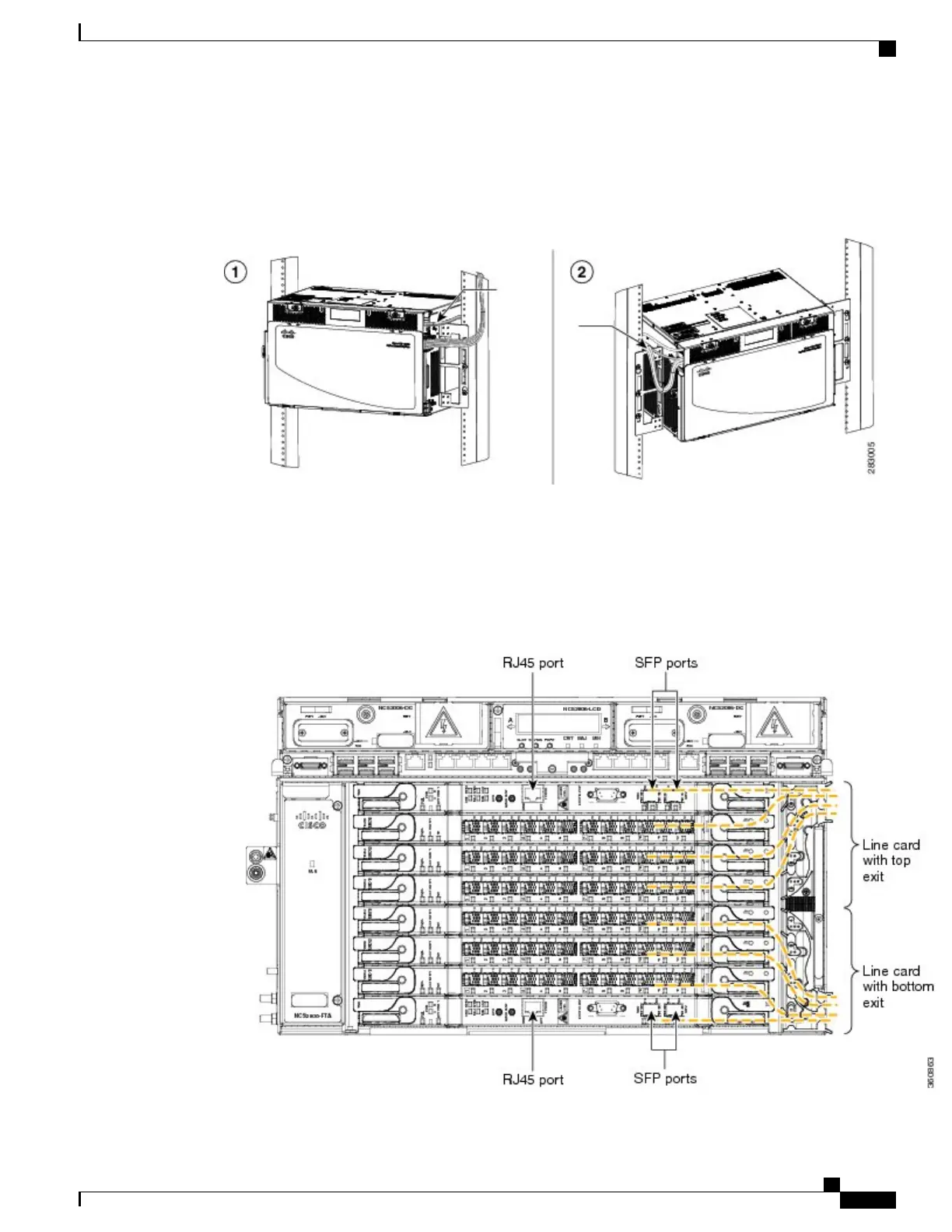
Figure 131: Cable Management
Step 2
Fix the cables using the tie-wrap provided in the accessories kit.
Step 3
To route the optical patch cords or copper cables, do the following as necessary:
a) Route the optical patch cords from the line cards through the fiber or cable module as shown in the figure
below .
Figure 132: Cable Routing
Cisco NCS 2000 Series Hardware Installation Guide
227
Connecting and Routing the Cables
DLP-L25 Routing and Locking Cables