b) Remove the front door and connect the copper cables to the SFP or RJ-45 ports of the cards. Do not route
the copper cables from the SFPs or RJ-45 ports through the fiber or cable module.
Step 4
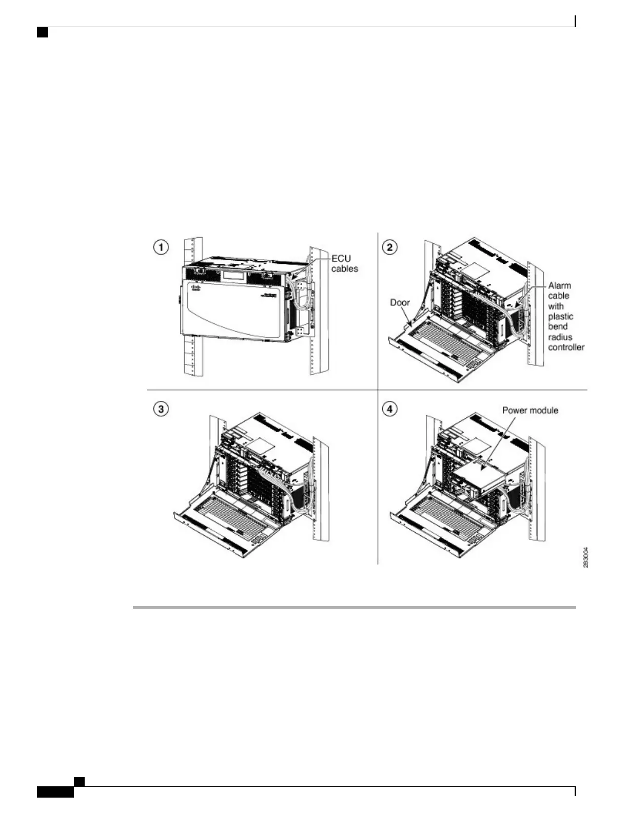
To extract the power module, do the following:
a) Open the door of the chassis. See Diagram 2 of the figure below .
b) Move the ECU cables away from the chassis. Ensure that the alarm cable with the plastic bend radius
controller is not moved. See Diagram 3 of the figure below .
c) Remove the power module. See Diagram 4 of the figure below .
Figure 133: Sequence to Remove the Power Module
Step 5
Return to your originating procedure (NTP).
Cisco NCS 2000 Series Hardware Installation Guide
228
Connecting and Routing the Cables
DLP-L25 Routing and Locking Cables