a) To verify the power, place the black test lead of the voltmeter to the frame ground. Place the red test lead
on the A-side connection and verify that it is between –40.5 VDC and –72.0 VDC. Place the red test lead
on the B-side connection and verify that it is between –40.5 VDC and –72.0 VDC.
For nominal steady state voltage of –48 VDC, the operating voltage range for the chassis is –40.5
VDC (minimum) to –57.6 VDC (maximum).For nominal steady state voltage of –60 VDC, the
operating voltage range for the chassis is –50.0 VDC (minimum) to –72.0 VDC (maximum).
Note
b) To verify the ground, place the black test lead of the voltmeter to the frame ground. Place the red test lead
on the A-side return ground and verify that no voltage is present. Place the red test lead on the B-side
return ground and verify that no voltage is present.
Step 2
To power up the shelf, insert the fuse into the fuse position according to site practice. The fuse rating must
not exceed 60 A.
Step 3
Using a voltmeter, verify the NCS 2015 shelf for –48 VDC or –60 VDC battery and return:
a) To verify the A-side of the shelf, place the black lead of the voltmeter to the frame ground. Place the red
test lead to the –48 V or –60 V (A-side battery connection) red cable. Verify that it reads between –40.5
VDC and –72.0 VDC. Then place the red test lead of the voltmeter to the RET1 (A-side return ground)
black cable and verify that no voltage is present.
For nominal steady state voltage of –48 VDC, the operating voltage range for the chassis is –40.5
VDC (minimum) to –57.6 VDC (maximum).For nominal steady state voltage of –60 VDC, the
operating voltage range for the chassis is –50.0 VDC (minimum) to –72.0 VDC (maximum).
Note
b) To verify the B-side of the shelf, place the black test lead of the voltmeter to the frame ground. Place the
red test lead to the –48 V (B-side battery connection) red cable. Verify that it reads between –40.5 VDC
and –72.0 VDC. Then place the red test lead of the voltmeter to the RET2 (B-side return ground) black
cable and verify that no voltage is present.
If the NCS 2015 shelf is being powered at –60 VDC nominal voltage, the door must be kept
closed during regular operations.
Note
Step 4
Repeat Steps 2 and 3 for each power module that is to be powered up.
Step 5
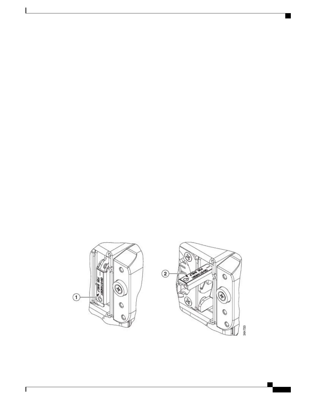
Set the power switch to ON position after lifting its cover. The power switch is present at the top right corner
of the chassis, next to the power modules. See the figure below.
Figure 198: Power Switch on the NCS 2015 Shelf
Cisco NCS 2000 Series Hardware Installation Guide
345
Connecting Power and Ground
DLP-L80 Turning On and Verifying DC Office Power on the NCS 2015 Shelf