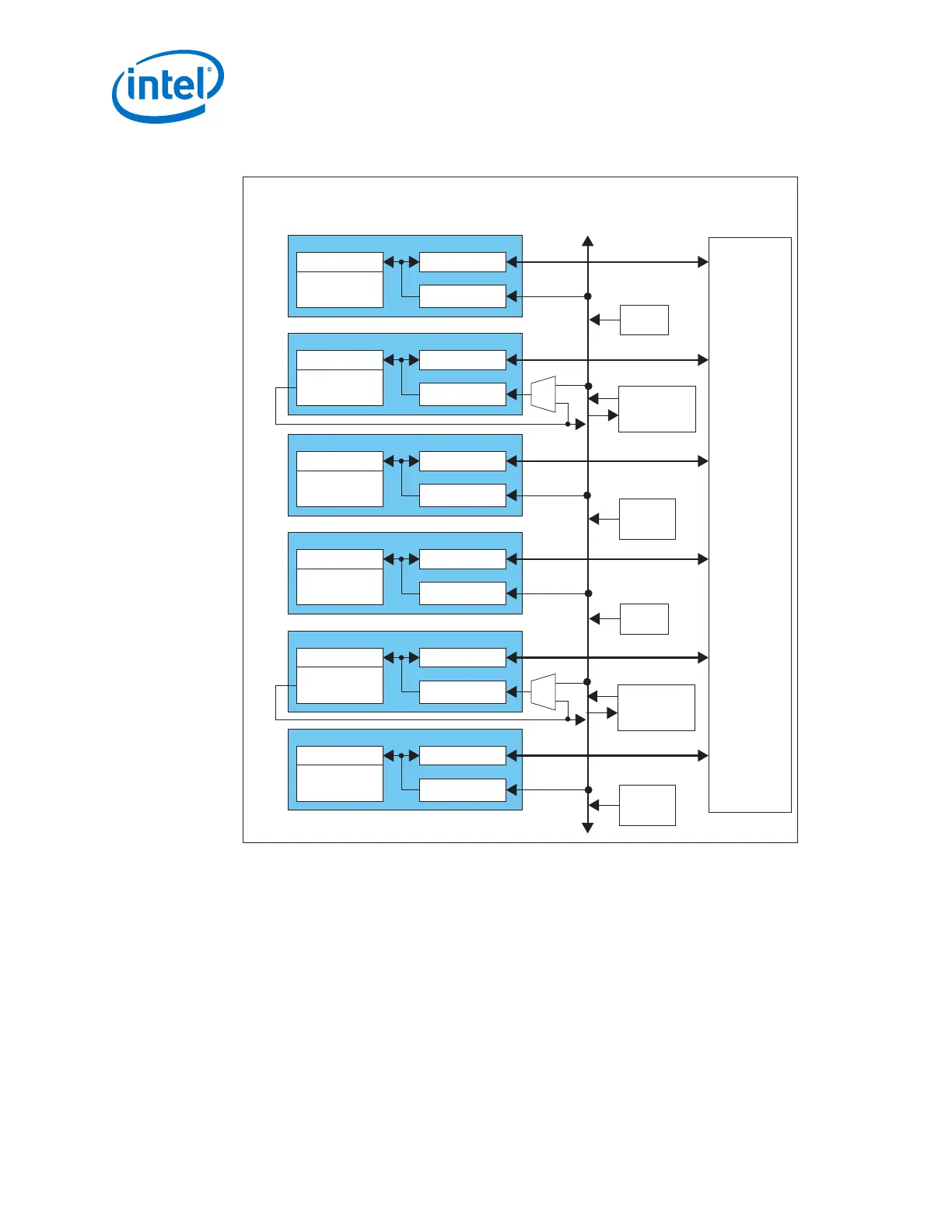
Figure 13. Six-Channel GX Transceiver Bank Architecture
PMA
Channel PLL
(CDR Only)
PCS
Local CGB5
CH5
PMA
Channel PLL
(CMU/CDR)
PCS
Local CGB4
CH4
PMA
Channel PLL
(CDR Only)
PCS
Local CGB3
CH3
PMA
Channel PLL
(CDR Only)
PCS
Local CGB2
CH2
PMA
Channel PLL
(CMU/CDR)
PCS
Local CGB1
CH1
PMA
Channel PLL
(CDR Only)
PCS
Local CGB0
CH0
FPGA Core
Fabric
Clock
Distribution
Network
Six-Channel GX Transceiver Bank
fPLL1
Master
CGB1
Master
CGB0
ATX
PLL0
ATX
PLL1
fPLL0
Note: This figure is a high level overview of the transceiver bank architecture. For details
about the available clock networks refer to the PLLs and Clock Networks chapter.
1. Arria
®
10 Transceiver PHY Overview
UG-01143 | 2018.06.15
Intel
®
Arria
®
10 Transceiver PHY User Guide
22