a.
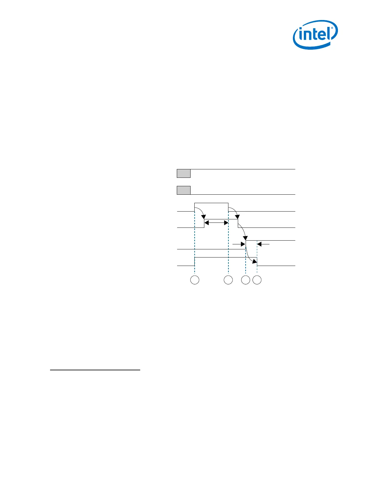
To ensure successful assertion of rx_analogreset, wait for
rx_analogreset_ack to go high. rx_analogreset_ack goes high when
the TRS has successfully completed the reset request for assertion.
b.
Deassert rx_analogreset.
2.
To ensure successful deassertion of rx_analogreset, wait for
rx_analogreset_ack to go low. rx_analogreset_ack goes low when the TRS
has successfully completed the reset request for deassertion.
(60), (61)
3.
Wait for rx_analogreset_ack to go low; then ensure rx_is_lockedtodata
signal goes high after the CDR (automatic lock mode) is locked to data.
4.
After rx_is_lockedtodata goes high, wait a minimum of t
LTD
(minimum of 4
μs). Then deassert rx_digitalreset.
Figure 213. Dynamic Reconfiguration of Receiver Channel During Device Operation
Device Power Up
rx_cal_busy
rx_analogreset
rx_is_lockedtodata
rx_digitalreset
rx_analogreset_ack
Legal
Reconfiguration
Window
1 2 43
t
LTD
min 4 μs
(60)
If the CDR operates in manual lock mode, step 3 on page 431 and step 4 on page 431 are not
applicable. After rx_analogreset_ack goes low, apply the reset sequence from the "Reset
Sequence Timing Diagram for Receiver when CDR is in Manual Lock Mode" figure below.
(61)
If the receiver signal detector is enabled and the CDR operates in manual lock mode, step 3 on
page 431 and step 4 on page 431 are not applicable. After rx_analogreset_ack goes low,
wait for rx_std_signaldetect to go high. When rx_std_signaldetect is high
continuously for 1 μs or more, apply the reset sequence from the "Reset Sequence Timing
Diagram for Receiver when CDR is in Manual Lock Mode" figure below.
4. Resetting Transceiver Channels
UG-01143 | 2018.06.15
Intel
®
Arria
®
10 Transceiver PHY User Guide
431